

NACE International has reported that, annually, “the cost of corrosion in the water and wastewater sector is approximately $58.5 billion.” One step toward lowering this vast sum is for design engineers, and collection system and treatment plant operators to continue to improve their understanding of the corrosion mechanisms potentially affecting wastewater system assets. With such understanding will come more sustainable designs for new installations and for systems being rehabilitated. These designs will lead to improved performance and operating life of existing assets. This paper provides brief but useful explanations and examples of corrosion mechanisms common to wastewater systems.
In municipal wastewater systems, the complexity and variety of corrosion mechanisms has often been overlooked. More often, corrosion has simply been “joined at the hip” with odor: where odor occurs, the hydrogen sulfide producing that odor also leads to corrosion of metals and concrete. Further, if you address and eliminate the odor problem, you will solve the corrosion problem, as well. Even within the Water Environment Association of Texas (WEAT), the focus on corrosion remained somewhat hidden in the Air Quality and Odor Control Committee. However, as wastewater infrastructure has continued to age, and condition assessments and asset management programs have shed light on the extent of corrosion within that infrastructure, the importance of corrosion in design and operations has continued to grow. In 2015, NACE International (formerly the National Association of Corrosion Engineers) formed a Water/Wastewater Advisory Council to advise NACE International in the development and implementation of a comprehensive corrosion program designed for the water and wastewater industry. Further, in the fall of 2016, WEAT renamed its Air Quality and Odor Control Committee the Odor and Corrosion Management Committee.
Corrosion is found in all corners of municipal wastewater collection systems and water resource recovery facilities (WRRFs), and includes, but is not limited to, the following mechanisms:
In WEF’s 6th edition of its Manual of Practice 8, Design of Water Resource Recovery Facilities, Chapter 10 – Materials of Construction and Corrosion Control helps readers truly appreciate the extent and variety of corrosion possible in these systems.
We cannot begin to cover here all of the important aspects of the corrosion mechanisms listed above. Thus, this paper will focus on some of the most commonly encountered corrosion mechanisms common to wastewater assets:
Biogenic sulfide corrosion affects concrete and steel in in collection system piping, tunnel structures, pump station wet well headspaces and in WRRFs. This process starts with bacterial sulfide formation followed by bacterial metabolism of hydrogen sulfide, H2S, to form H2SO4, sulfuric acid.
Domestic sewage contains an ample supply of sulfate ions (SO4=), which may be reduced by sulfate reducing bacteria (SRB) that live within slime layers that form on sewer surfaces. The SRB’s require an anaerobic environment that may form after one to three weeks in the slime layers at thicknesses sufficient to exclude oxygen. The SRB’s use the oxygen from the sulfate ions for metabolizing organic species in the wastewater, and produce sulfide, S=, as a byproduct. That sulfide then forms bisulfide, HS–, or H2S, depending on the pH. The H2S comes out of solution, especially at areas of turbulence, entering the atmosphere and causing odors. The H2S may also react with oxygen to form sulfurous acid on surfaces in the vapor space. Carbon dioxide (CO2), released from the wastewater, also condenses and forms weak carbonic acid which lowers the surface pH.
As the surface pH is decreased or acidified, sulfur oxidizing bacteria (SOB) colonize the surfaces if sufficient moisture and oxygen are present. The nutrient rich scum layer just above the water line meets the needs of these bacteria especially well. These bacteria use dissolved oxygen to metabolize the H2S, which is oxidized to sulfuric acid, H2SO4. Different strains of SOB predominate as the pH decreases to less than pH 1.
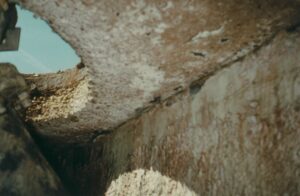
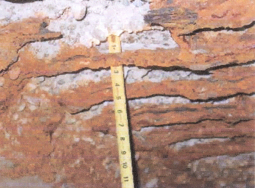
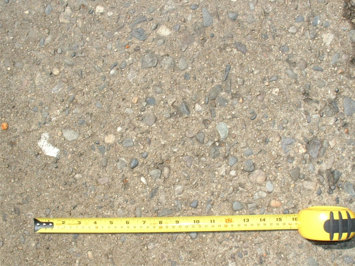
Biogenic sulfide corrosion of concrete involves dissolution of hydrated cement paste by sulfuric acid, resulting in deterioration of the concrete matrix and exposure of the coarse aggregate, as illustrated in Figures 1 and 2. The sulfuric acid attacks the highly alkaline Portland cement, reacting with the calcium hydroxide to form calcium sulfate, or gypsum. The gypsum is a soft, yellowish white paste that can be easily removed by turbulent flow.
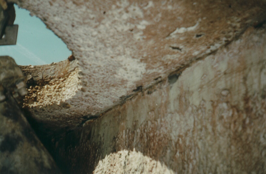
The rates of degradation of concrete in wastewater systems depend on the H2S concentration in the headspace, original concrete permeability (quality) and other factors. Typically, when H2S gas concentrations in headspaces have been between 25 and 50 ppm, the rate of cement past losses have been between 1/16 and 1/8” per year. Unprotected steel surfaces also are rapidly attacked in these highly acidic environments (see Figure 3).
Control of biogenic corrosion is possible via selection of protective coatings, specified and installed correctly. The properties of coatings should be confirmed by testing according to ASTM standards, which can determine water resistance and permeability of prospective coatings. Abrasive conditions and velocity effects must be evaluated. Substrate condition, moisture conditions, temperature and time to cure are critical factors in coating application, and must be enforced to achieve the expected results. Future inspection and maintenance can ensure that the coatings provide long-term protection.
In addition to coatings, protective linings are widely used to protect concrete. These linings may be cast-in-place, chemically attached with mastic ‘glue’ or mechanically anchored to the substrate.
Carbonation occurs in all concrete that is exposed to the atmosphere or to carbonated waters. Carbon dioxide (CO2) reacts with the hydrated constituents of Portland cement paste, particularly calcium hydroxide (Ca(OH)2) via the following reaction:
Ca(OH)2 + CO2 à CaCO3 + H2O
That is, calcium hydroxide and carbon dioxide react to form calcium carbonate plus water. The carbon dioxide is produced by decomposition of organics by aerobic bacteria in the recovery facility reactors or aerators. The actual reactions are more complex, with several other reactions between CO2 and the other constituents of the hydrated cement paste. What is important is that these reactions produce carbonates, and this invariably results in shrinkage of the cement paste.
Carbonation also occurs in concrete where CO2 has been absorbed by water, producing carbonic acid. The rate of carbonation in hardened concrete increases if the concrete is more permeable. The permeability of the concrete is influenced by the water/cement ratio, temperature, concentration of CO2 in the water, and the hardness and alkalinity of the water. Liquid-phase carbonation in water occurs in wastewater treatment plant structures, primarily in aeration tanks, oxygen reactors, and other closed tanks such as primary and secondary clarifiers. It is more common in oxygen reactors where the dissolved CO2 concentrations are greater due to the partial pressurization of the headspaces.
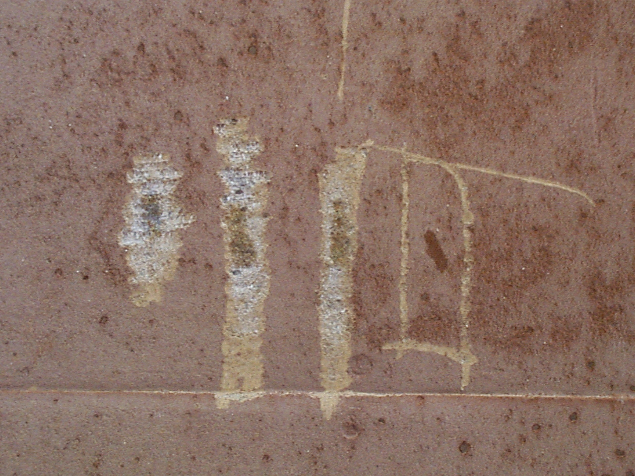
The rate of cement paste attack by liquid-phase carbonation is generally very slow—typically about 1/16 to 1/8” depth of loss in the first one or two years of exposure. Due to the pore-blocking effects of calcium carbonate and water, this rate slows down after the first couple of years. After 25 to 30 years of service, cement paste losses can be ½ to ¾”. Turbulent flow can wash away the carbonated paste, exposing the surface to further carbonation. The high solubility of calcium carbonate exacerbates the flow effect. Figures 4 and 5 are typical of this type of damage seen in concrete in WRRF’s. Coatings and linings can be employed to prevent or to repair damage.
Aqueous-phase carbonation of concrete is best prevented via improvement to concrete density, such as through use of micro-silica-modified concrete made with the lowest possible water-to-cementitious materials ratio (W:CM), or with barrier protection provided by coatings or linings.
Concrete, which when newly hydrated has a pH around 12.5, is protective to carbon steel reinforcing steel. When the wet concrete mix is placed around the steel, the alkaline paste lightly corrodes the surface of the steel to form a tightly adherent, protective oxide film on the steel. This protective layer can be damaged when moisture, oxygen and chlorides penetrate the concrete through permeation or cracks. Some areas of the reinforcing steel become anodic to other areas, resulting in corrosion.
Corrosion of the steel results in formation of corrosion products that have a larger volume than the original steel, and this expansion cracks the concrete. The cracks then accelerate the damage by offering new paths for moisture and corrosive species such as chlorides. Once corrosion has started, iron cations and hydroxide anions combine to form iron hydroxides and oxides and form hydrogen ions (H+), which acidifies the aqueous solution. The H+ ion attracts more chloride (Cl–) into the area to balance charges, thereby forming HCl, hydrochloric acid, which accelerates the corrosion. Chloride in municipal systems often originates from infiltration of brackish or salt water into the collection system.
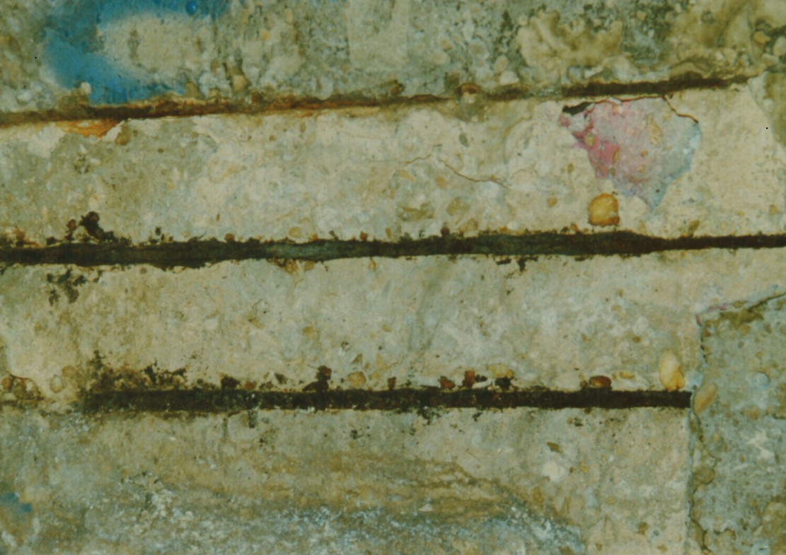
Corrosion of reinforcing steel is often first revealed as rust bleed on the outer concrete surface, and this is followed by cracking and spalling. A layer of concrete may spall off to expose the rebar, as seen in Figure 6. Chloride-induced rebar corrosion in wastewater treatment systems occurs in vapor-phase areas that are subjected to cyclic wetting and drying conditions. Below the water line, sulfates and other precipitates, mainly from carbonation, have a pore-blocking effect that slows chloride and oxygen diffusion into the concrete. In lift stations, collection conduits, siphons, and in other chambers that experience varying flow elevations, chloride-induced rebar corrosion can cause severe degradation in 5 to 7 years.
Chloride-induced reinforcing steel corrosion occurs widely in pump stations of coastal collection systems. It is also often encountered where sodium hypochlorite is handled or used, as in disinfection basins. In addition, it can occur where ferric chloride is handled or used for chemical treatment.
Perhaps the most common prevention method for chloride-induced corrosion in concrete or of exposed ferrous metals is via the application of the right protective coatings or linings. Reinforcing steel can also be protected by electrochemical means, that is, cathodic protection. The protection may be applied by tying the rebar together electrically to anodes, to shift the corrosion to the anode, thereby protecting the rebar. Sacrificial anodes such as magnesium or zinc may be used, then replaced periodically; or impressed current systems may be used with a mixed-metal-oxide or high-silicon cast iron anode. Any of these systems requires careful design and on-going inspection and maintenance.
Stainless steels have found increasing use in wastewater systems due to their low general corrosion rates. However, the commonly used 304L and 316L austenitic grades are susceptible to localized corrosion: pitting, crevice corrosion and stress corrosion cracking. This damage can lead to unexpected leaks or ruptures after a surprisingly short time in service. The chromium and nickel alloying produces the superior general corrosion resistance, and addition of about 2% molybdenum to 316L imparts some resistance to pitting and crevice corrosion compared with 304L grade. More highly alloyed stainless steels may contain 6% molybdenum or more, and they are commensurately more resistant to localized corrosion.
Another type of stainless steel, the duplex grades, have a different microstructure composed of a combination of ferrite (like carbon steel) and austenite (like the 300-series stainless grades). This duplex structure resists chloride stress corrosion cracking better, and the pitting resistance is comparable to the 300-series. Type 2205 is perhaps the best known grade of duplex. Lean grades such as 2304 and 2101 offer economies for certain services, and 2507 is a highly alloyed duplex utilized in corrosive environments including brines and seawater.
Pitting occurs in the 300-series stainless steels in waters containing threshold concentrations of chloride. As a rule of thumb, 304L is regarded as resistant up to 300 ppm chloride concentration and 316L up to 1000 ppm in neutral-pH waters. A number of other factors such as temperature, pH and flow rate can have significant effects on corrosion rate. Pitting is associated with a local discontinuity in the passive film. It could be a mechanical discontinuity such as a rough weld or grinding damage. It can also be caused by local chemical breakdown of the film, the most common chemical agent being chloride. Chloride becomes incorporated into the passive surface films that protect the stainless steels, and weaken the film, so attack can initiate the formation of a pit. As corrosion occurs, hydrogen ions are produced as a byproduct of the formation of hydroxide corrosion products. That localized acidification increases the corrosion rate, and the hydrogen ions (H+) attract more chloride to balance the charge. Once a pit forms, the environment inside of it can be enriched with chloride and acidified. The pit now is an anodic area, with the surrounding surface the cathode, so attack becomes concentrated within the pit.
In a similar fashion, crevices present a place for a locally corrosive environment to develop. Crevices are formed by joints like flanges or threaded connections. In some conditions, heavy deposit accumulations on a stainless steel surface act like crevices. Microbiological growths composed of slime layers and silt may form a barrier that acts like a crevice. The pH within crevices can drop to as low as 2, accelerating corrosion accordingly.
Resistance to chloride pitting and crevice corrosion is influenced by addition of alloying elements chromium, molybdenum and nitrogen. The relative influence of each element can be summed up to determine an index value called the pitting resistance equivalent number (PREN) expressed by:
PREN = %Cr + 3.3·%Mo + 16·%N
Table 1 summarizes the PREN for several popular grades of austenitic and duplex stainless steels. The PREN provides a guide for ‘alloying up’. If the chloride level is excessive for 316L, then a higher-PREN alloy can be selected.
| Alloy | %Cr | %Mo | %N | PREN |
| 304L | 18 | 0 | 0 | 18 – 20 |
| 316L | 17 | 2.2 | 0.06 | 23 – 28 |
| 2304 | 23 | – | 0.10 | 26 |
| 2205 | 22 | 3.0 | 0.15 | 31 – 38 |
| 317LMN | 17 | 4.5 | 0.10 | 32 – 40 |
| 2507 | 25 | 4.0 | 0.30 | 38 – 46 |
| 254SMO | 20 | 6.1 | 0.20 | 42 – 47 |
| AL6XN | 20.8 | 6.2 | 0.22 | 43 – 48 |
| 654SMO | 24 | 7.3 | 0.50 | 63 |
In chloride-containing environments in hot climate conditions (Arizona, Nevada, Texas, Florida, New Mexico, or arid areas of California) the chloride concentration at or just above the water line can be doubled or tripled by the concentration effect of wet-dry cycling. The stainless steel should be selected to take this into account.
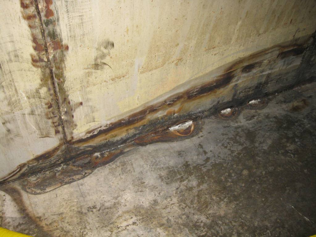
It should be noted that the corrosion resistance of welds is frequently poorer than the base material. For this reason, weld materials are often upgraded to an alloy with a higher PREN than that of the base material. A PREN at least 5 higher than the base metal is usually sufficient. For example, when using 316L, a 317LMN welding electrode may be recommended. All heat tint should be removed from welds to ensure the expected corrosion resistance. Figure 7 illustrates corrosion of the welds in a stainless steel tank where the weld heat tint had not been removed. Note also the rusting on the vertical weld due to carbon steel contamination during weld preparation (grinding).
Chloride stress corrosion cracking of 304L and 316L stainless steels may occur if the temperature is above 120 to 140°F in a neutral-pH environment. It typically is not a significant problem in municipal water and wastewater systems but can be more of a problem in systems that handle industrial effluent, which often contains higher concentrations of chloride. Duplex stainless steels may be resistant to 250 to 285°F.
Prevention of pitting and crevice corrosion of stainless steel starts with good design. Piping and tanks must be configured to drain fully. Crevices at bolted connections between structural sections, flanges or laminated sections should be minimized. If deposit accumulations are anticipated, then horizontal surfaces like ledges should be sloped.
Operating practices can be reviewed to make sure that infrequently used lines are drained, that velocities are sustained at levels that discourage deposit formation, and chemistries can be maintained below chloride and temperature thresholds for a given alloy. These limits sometimes should be confirmed through laboratory or field coupon testing. If pitting and crevice corrosion are allowed to initiate, then stopping them can be very difficult because the pits and crevices have by then developed localized, highly corrosive environments protected underneath hard deposits or beneath the metal surface.
Microbiologically-influenced corrosion (MIC) is the result of changes in the local environment caused by the metabolism of microbes on the metal surface. The presence of micro-organisms may increase the corrosion potential of the steel, that is, the electrochemical potential of the surface resulting from the balanced anodic and cathodic reactions. This is known as ennoblement. The increased corrosion potential will cause higher pitting and crevice corrosion risk.
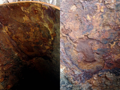
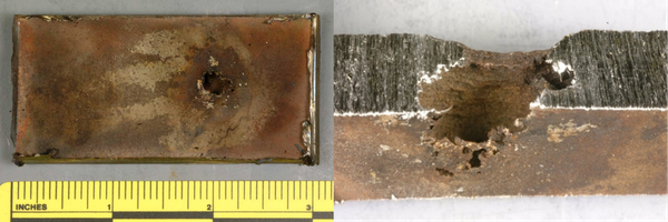
MIC in wastewater applications is usually the result of anaerobic bacteria. SRB’s, as introduced in the earlier discussion on biogenic sulfide corrosion, are always present in the ‘slime layer’ or biofilm formed naturally in sewer collection systems. These bacteria form and release hydrogen sulfide and create acid conditions underneath deposits resulting in pitting and crevice corrosion. This damage typically occurs below the waterline as opposed to the headspace degradation of concrete and ferrous metal associated with sulfur oxidizing bacteria (SOB). Figures 8 and 9 illustrate MIC damage in WRRF service. Note the subsurface morphology of the pits.
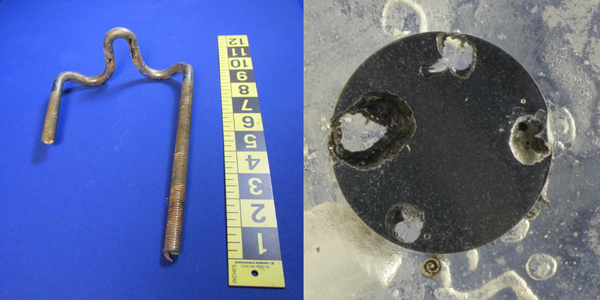
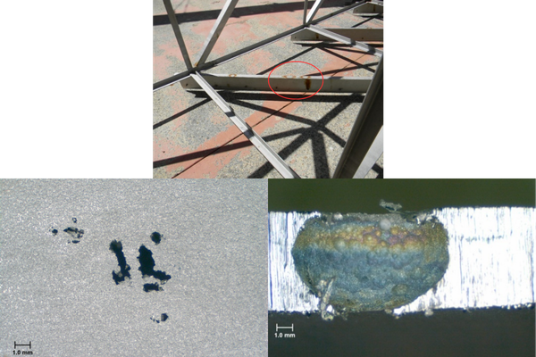
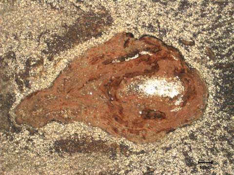
Corrosion product tubercles formed by MIC are often observed. The tubercles are typically cone-shaped. An outer crust is composed of iron oxides and mineral, and there is an inner shell, a corroding floor and a fluid-filled cavity. The undersides of the tubercles are blacker than the reddish-brown color on the surface exposed to the process water. The pH is lower and the chloride concentration higher inside the tubercle. Pits in 300-series stainless steel components are illustrated in Figures 10 and 11, where tubercles have been removed. The area of active corrosion is shiny.
Avoiding localized corrosion of stainless steels in wastewater environments requires careful alloy selection and the execution of tried-and-true fabrication and post-weld cleaning practices.
Corrosion in wastewater systems encompasses a wide variety of mechanisms that can lead to often rapid deterioration of metal and concrete equipment and structures. Process and environmental conditions that cause corrosion vary significantly between and within WRRFs and collections systems, as do suitable control and prevention strategies. The few examples of corrosion mechanisms presented here provide but a glimpse of the issues that face designers and operators. Preventing this costly deterioration requires a sound understanding of the corrosion mechanisms. Selecting and implementing the appropriate mitigation methods for each damage mechanism in a specific application demands the right experience and careful attention to detail. All of this, along with design practices that foster consideration of corrosion early in the process, will go a long way toward reducing the occurrence and total cost of corrosion in this part of our nation’s infrastructure.