

Fiberglass reinforced plastic (FRP) odor control ductwork and equipment, if properly designed, constructed and operated, should perform well for up to 50 years of service life in municipal wastewater treatment plants. However, the use of the wrong resin or curing practices can result in chemical breakdown of the corrosion barrier. Improper joining work at hand laid-up butt-and-strap joints can make the structural laminate vulnerable to chemical attack and loss of structural integrity. Additionally, excessive grit carryover from grit-removal units can cause significant corrosion barrier damage to FRP ductwork, resulting ductwork leakage and failure. These are only a few of the potential problems that can reduce the expected useful service life of FRP odor control equipment.
This paper will discuss condition assessment methods recommended for FRP ductwork and equipment based on matching the typical damage mechanisms or defects that occur to the best-suited condition assessment methods.
Assessment methods, including internal and external visual inspection, laminate sequence sampling and testing, resin type confirmation, microscopic examination, glass content testing, hardness measurement, physical property testing, and laminate thickness measurement, will be discussed and demonstrated with photographs. The importance of each assessment task will be explained, and the comparison of condition findings to the design and performance specification requirements for quality will be emphasized.
Introduction
Fiberglass reinforced plastic (FRP) is the most widely and successfully used material of construction for odor control ductwork and equipment in municipal wastewater applications. If the appropriate materials are selected and the fabrication and installation of this equipment and ductwork are properly specified and executed, FRP provides exemplary performance in these service conditions. Achieving the requisite quality for such outstanding material performance requires attention to detail in design, fabrication and installation. Once in service, FRP ductwork and equipment, including scrubbers, carbon absorbers, and other FRP equipment, needs to be periodically assessed to help assure its expected in-service performance. This paper presents the typical damage mechanisms and causes of premature degradation associated with FRP odor control ductwork and equipment. The discussion then turns to matching the appropriate condition assessment methods to those expected and commonplace damage mechanisms and defects.
Most FRP ductwork and equipment deterioration in odor control systems involves one or more of the following causal factors or damage mechanisms:
• Improper material selection, especially the FRP resin type.
• Inadequate design considerations for structural support.
• Poor fabrication practices.
• Improper field joining practices.
• Operational conditions that exceed the design criteria, and which promote premature degradation in the FRP laminate.
This paper provides technical guidance on where and how to inspect for deterioration or damage in FRP odor control equipment considering each of the causal mechanisms or contributing factors listed above. Examples of each type of degradation are explained and depicted for reference. In particular, assessment methods including both inspection watch-outs and laboratory tests are described, which provide the necessary insight into the expected service life of these important FRP assets.
FRP material is made by mixing and combining liquid resin and fibrous reinforcing components to produce a cured, solid material with the desired properties. Unlike with metal alloys and thermo-plastics, the material is created as the equipment is fabricated. A major consequence is that the properties of the FRP laminate materials can vary, depending on how much care and control are exercised when the laminate is constructed. Chemical resistance is provided by the resin matrix; strength is provided by the oriented, encapsulated fibers of glass. Components of the laminate include a glass or synthetic veil, chopped (fiberglass) strand mat (CSM), and filament-wound strands of glass called woven roving (WR).
The two most commonplace FRP construction methods for odor control equipment are as follows:
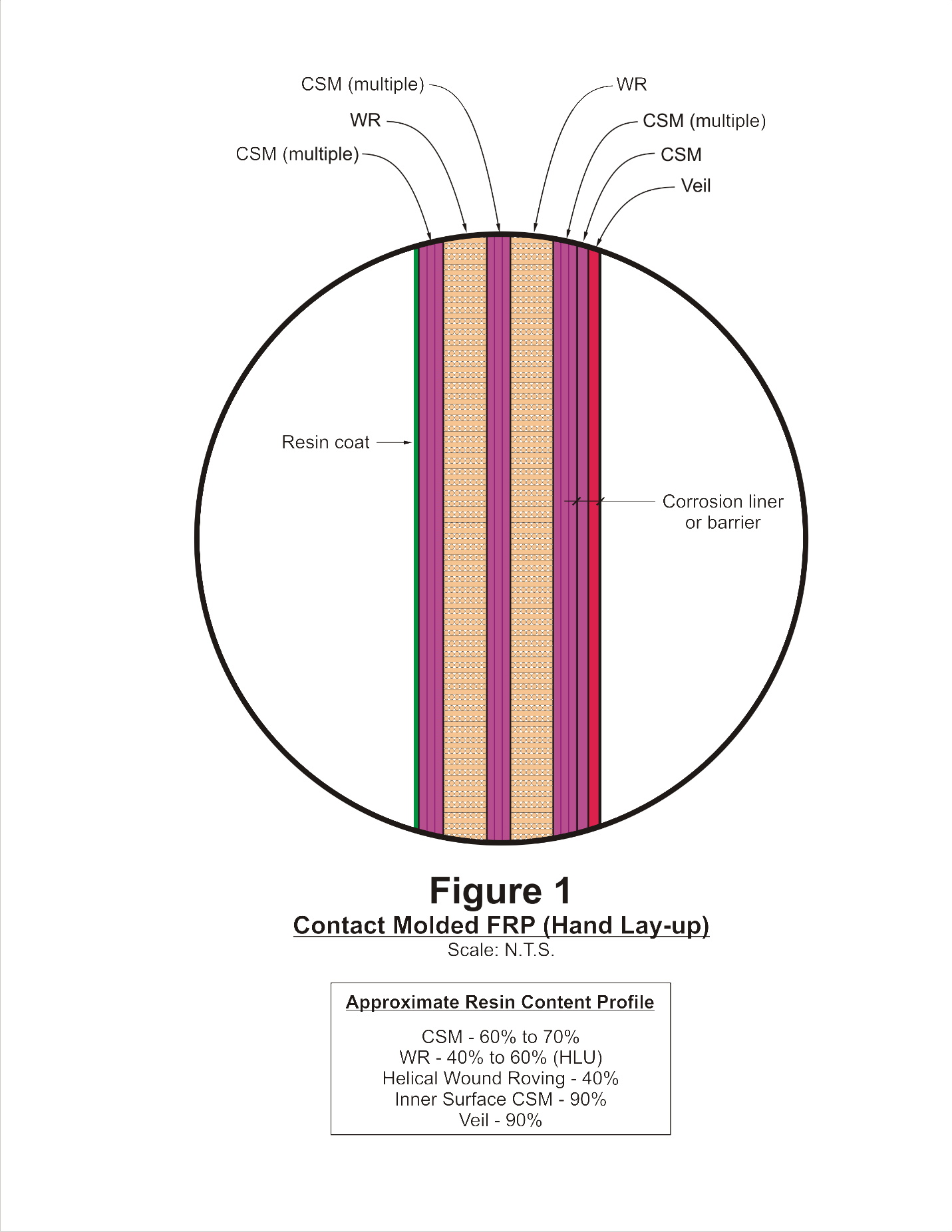
Hand Lay-Up (HLU) or Spray-Up (SU) Construction. This method is also called Contact-Molded Construction. HLU and SU laminates are made in round, square, and rectangular shapes, and are also used to make transitional shapes for round-to-square connections. Figure 1 shows a typical cross-sectional view of HLU laminate construction. HLU construction consists of alternating layers of resin-impregnated CSM and WR in a predetermined sequence to create a solid laminate (after the resin cures) with the specified thickness and mechanical properties. The corrosion barrier is made using a glass or synthetic veil for resin-rich retention.
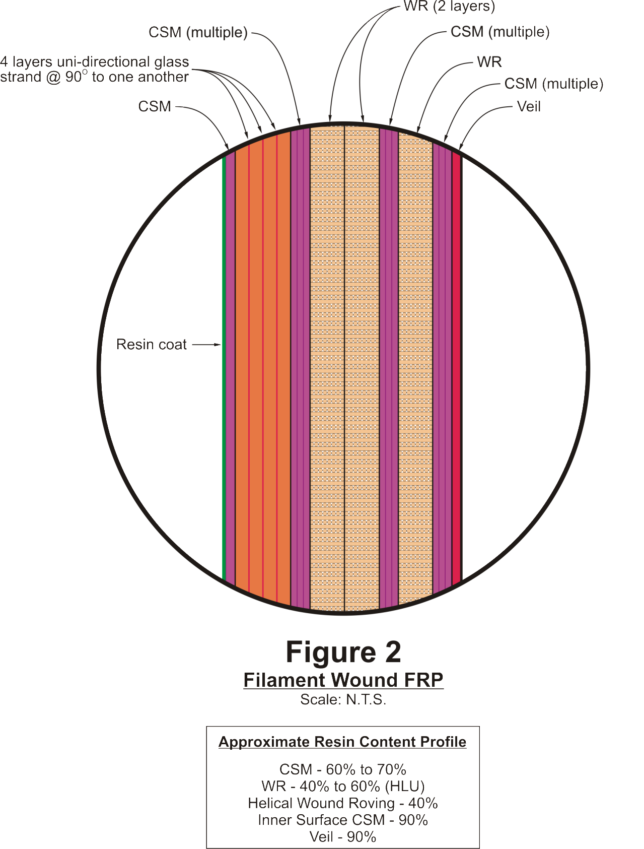
Filament-Wound (FW) Construction. FW construction is widely used for both ductwork and cylindrical tank construction. Figure 2 depicts a typical FW laminate construction cross-section. This method involves automated helical winding of continuous fiber-glass threads wet with resin onto a cylinder, to produce cylindrical “cans” of specified thickness. FW construction consists of continuous WR for the structural wall. Winding angle determines axial and hoop strengths. The corrosion barrier or liner for FW equipment is typically made by hand lay-up or other contact-molded methods.
Most scrubbers and carbon absorbers are constructed using contact-molded fabrication methods due to their geometry. This includes HLU and SU fabrication techniques.
Their higher glass content gives FW laminates higher strength-to-thickness ratios, but lower chemical resistance and higher permeability than HLU laminates.
For both construction methods, the corrosion barrier or liner’s inner layer typically has >80% resin content (the veil-reinforced inner surface often has >90% resin). The structural laminate or wall generally contains 30 to 70% resin depending on the laminate design and how the structure was constructed.
All FRP laminate construction (whether FW or HLU) includes two major construction elements:
• The structural wall laminate that provides the shape and strength of the structure. Depending on the structural calculations for a given ductwork or equipment component, the number and sequence of the various reinforced layers of WR and CSM will vary.
• The corrosion liner, or barrier, which protects the process side of the structural wall from chemical attack or penetration by liquid or gaseous process contaminants or corrodents.
The greatest differences between the structural wall laminate and the corrosion liner include their resin-to-glass reinforcement ratios and the types of glass (or alternate synthetic material) reinforcement used within the two elements.
The corrosion barrier or liner typically consists of the inner surface, which has a high resin content and is reinforced with a glass or synthetic veil (typically 0.01 to 0.02 inch thick at the interior layer), and layers of CSM and resin (typically 0.1 inch thick).
The structural wall is reinforced with CSM (or strands when sprayed-up), WR, or combinations of these reinforcement types. An exterior corrosion layer is often included on the structural wall to protect against corrosive spillage or leakage from the equipment and ultraviolet radiation (UV) attack. This layer generally is built with CSM and resin, similar to the interior layer of the corrosion barrier or liner, but without a veil. This is often standard on well-built FRP equipment and ductwork.
Three methods of joining FRP parts or components are most commonly used in odor control equipment. They are as follows:
Butt Joints (also called butt-and-strap joints). Components are butted together and are over-wrapped by HLU methods to form a splint type of joining. This requires careful cleaning and abrasion of the parent FRP component surfaces to be joined to ensure good bonding of the resin and reinforcement. Adhesion of wet FRP resin to cured resins relies on mechanical adhesion, rather than chemical adhesion. This is because the resins used are thermosetting resins and not thermoplastic resins. Resin and glass reinforcement are laid-up across the butted surfaces and subsequently sealed with resin overlapping onto the existing corrosion liner.
Bell-and-Spigot Joints. These joints are made for fitting one end of the component into the expanded end of the other component to which it is joined. The mating surfaces are first abraded to assure good mechanical adhesion. The joint is then filled with resin-based putty or paste and the parts are pushed together. After the excess paste is removed, it is typical to over-wrap the joint with resin and reinforcement using the HLU process, much like in the butt joint method.
Flanged Joints. Flanged joints are prefabricated for easy installation and to facilitate future access for in-service inspection or removal for maintenance. Flanged joints are generally used for ductwork manways, pipe nozzle connections, or nozzles for connections to scrubbers or absorbers. Flanged joints are constructed by HLU methods in the shop. When large flanged connections are needed, reinforcement plates of FRP are required on the vessel, tank, or ductwork wall at such connections. This helps avoid over-stressing the connection at the structure wall. Additionally, gussets are frequently used to add reinforcement to nozzles made in structures or vessel walls, again to prevent overstressing problems.
Improper Resin Material Selection or Curing Chemical Degradation. The typical operating condition for the interior of FRP odor control equipment involves exposure of the FRP surfaces to varying concentrations of hydrogen sulfide (H2S) gas, methane gas, carbon dioxide gas, various mercaptans, and wastewater liquid and biosolids particulate from airborne carry-over with air flow. Because H2S gas concentrations can be quite high, the FRP process-side surfaces are also exposed to dilute sulfuric acid formed by biogenic sulfide acid formation. It is widely agreed by materials engineers that the sulfuric acid concentration in these applications peaks at approximately 7.5%.
Empirically, it is well-known that brominated bisphenol A epoxy vinyl ester resins perform extremely well in odor control ductwork and associated foul air treatment equipment. This is the commonly specified resin type for this type of odor control equipment. Resins with less robust chemical resistance should not be used in these service conditions. Hence, the resins used in the FRP odor control equipment should be checked periodically to ensure there are no signs of resin chemical attack or breakdown.
If the FRP resin system used was improperly selected or cured, various forms of defects may be present. One should look for:
• Softening or weakening of the resin.
• Craze cracking of the resin in the corrosion liner.
• Delamination of the corrosion barrier from the structural laminate.
• Dissolution of the resin. This will be manifested by exposure of fiberglass reinforcement, which has been disengaged due to resin degradation.
• Blisters, delamination, and swelling of the laminate may also be tell-tales of chemical attack or breakdown. This is often the result of chemical permeation of the resin, which can occur if the resin is insufficiently corrosion resistant or is improperly cured. Photo 1 shows blistering of an improperly cured resin in the corrosion barrier in odor control ductwork.
Probing of the cured resin to discern if it is hard and well-cured is also essential to this assessment, as is looking for color changes in the FRP resin—another tell-tale of chemical degradation.
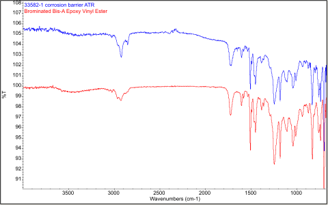
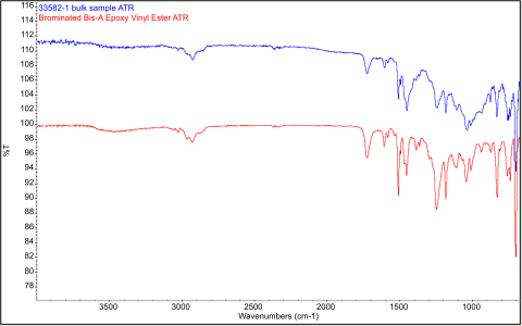
If the resin does appear to be softened or permeated and blistered, samples of the laminate should be removed for laboratory analysis. Chemical testing of the resin used in the degraded laminate is most expeditiously done using Fournier Transform Infrared Spectrographic (FT-IR) methods. FT-IR spectra of the degraded resin in the FRP equipment and a known exemplar for the appropriate resin (brominated bisphenol A epoxy vinyl ester) are compared using a computerized database for the exemplar. Refer to Figure 3, below, which shows a close spectral fit between an in-service FRP ductwork resin and the appropriately specified resin system. This comparison indicated that the appropriate resin was used in the laminate construction being evaluated.
Mechanical Damage. This is a common issue in FRP odor control equipment and ductwork. FRP, unlike metals, has little capability for deformation under load, therefore it does not yield like metals. Rather, overstress or mechanical impact damage generally result in fracturing of the laminate. To assess FRP equipment for mechanical damage, one should inspect areas that are subjected to high stresses. This includes looking for cracks in the following areas:
• Gussets
• Flanges for nozzles
• Interfaces between metal mechanical supports and the FRP (e.g., hangers, saddle supports, etc.)
• Knuckles at the bottoms of tanks or vessels
• Lifting lugs
• Metal embedments or FRP attachments for ladders or baffles, pipe supports, etc. (can be internal or external)
• Hold-down lug connections
In addition, star cracks, scratches or gouges, and depressions in the laminate are likely indicators of impact damage.
Environmental Exposure Damage. Exposure to direct sunlight, which contains UV radiation, causes most organic materials to degrade to some extent. With FRP, sunlight exposure does cause the resin to embrittle and deteriorate with time. UV-resistant additives are used in FRP, and these materials help its UV resistance, but not for a long period of time. Typically, coating the FRP with UV-resistant polyurethane or other specialty coatings is required to prevent long-term UV degradation.
When UV breakdown occurs, the FRP experiences resin bloom. The white show-through color of the glass fiber will be visible initially, followed ultimately by fiber exposure.
Shop Fabrication Defects. In FRP equipment, fabrication defects can include gel coat delamination on either side of secondary joints (laid-up in the field) or the effects of using an insufficient number of the right laminate layers of reinforcement in sequence, as designed. This results in insufficient thickness of the FRP laminate. Fabrication defects also include dry pockets (insufficient resin impregnation), inadequate sealing of cut edges, unintended inclusion of materials in the laminate (such as duct tape), misalignment of components during lay-up, or failure to remove the Mylar film used as the parting or bond breaker on the mold for contact-molded FRP equipment. These types of defects should be caught during fabrication QC efforts, but sometimes get missed.
Secondary Joints or Lamination Problems and Airborne Carryover of Wastewater Constituents. Discussed previously were the commonplace joining methods for FRP odor control ductwork and equipment. These are the potential weak links most generally found in FRP equipment. Because wet resin adhesion to cured resin relies on mechanical bonding to abraded profile in the cured resin, inadequate surface preparation or a lack of good resin wetting-out of the mating surfaces for the secondary joining lay-up often result in adhesion-related voids or leak paths into the joint. In odor control ductwork, this leads to significant performance problems. The leakage of biogenic-formed sulfuric acid finds its way through the corrosion barrier and into the structural laminate, which can cause resin and reinforcement separation. Also, this contamination means successful, future repair of the leaking joint will be nearly impossible. Ultimately, the acid makes its way through the laminate, often traveling along the spaces between the less-resin-rich structural wall layers or between the HLU layer and the parent FRP.
In addition, carryover of wastewater liquid and particulate, especially from grit classifiers, can often find its way into compromised secondary joints in ductwork and equipment. This particulate carryover can be the result of inadequate baffle design for ductwork intake; excessive airflow velocity at ductwork intake; or problems with the grit removal equipment itself. This carryover of grit can cause abrasive damage to the corrosion liner, later resulting in contamination of the structural wall laminate elements. This contamination, in turn, can result in leakage problems and, as previously noted, it precludes the possibility of proper laminate repairs. This is most commonly problematic in ductwork leading to scrubbers, biofilters, and later absorbers.
When evaluating the condition of FRP equipment, it is essential to assure that design and fabrication were performed in compliance with both the equipment specifications and all pertinent standards. For the specifications, the critical compliance checks are as follows:
• Proper resin use.
• Resin-to-reinforcement ratios.
• Laminate sequence.
• Minimum laminate thickness requirements for the corrosion liner and the structural wall.
• Surface hardness: the laminate should, when fabricated and cured, have a Barcol hardness of at least 90 percent of the manufacturer’s minimum specified hardness for the cured resin, when tested in accordance with ASTM D2583, Standard Test Method for Indentation Hardness of Rigid Plastics by Means of a Barcol Impressor.
• Minimum laminate tensile and flexural strength test values (for the new FRP equipment).
For in-service FRP odor control ductwork and equipment, it is crucial to recognize that FRP materials intrinsically lose strength properties over time. Hence, coupon removal and subsequent strength testing is extremely important in the condition assessment of in-service FRP. This test data should be compared to the originally specified strength values. As this loss in strength occurs, the follow-up testing should affirm that the FRP strength continues to meet the minimum specified values from design.
FRPI (Fiberglass Reinforced Plastics Institute) Standard Practice SP 9000, Laminating Process Certification should be used (if written into the project specifications) for certifying the FRP laminate process for the equipment. In addition, FRPI has developed guidelines and specifications that are extremely useful in assuring FRP quality assurance during fabrication and for certifying fabricators.
Other standards that should be reviewed for compliance prior to and during FRP equipment design and in-service inspections, when pertinent, are:
• NBS Voluntary Product Standard PS 15-69, Custom Contact-Molded Reinforced-Polyester Chemical-Resistant Process Equipment
• ASME RTP-1, Reinforced Thermoset Plastic Corrosion-Resistant Equipment
Based on the damage mechanisms and defects (described above) most commonly found in FRP odor control equipment, the following condition assessment methods are recommended:
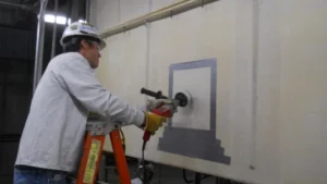
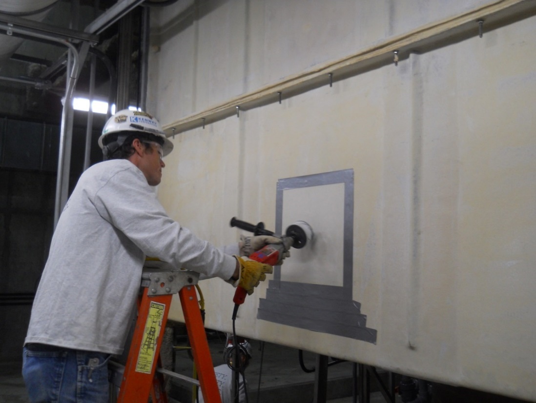
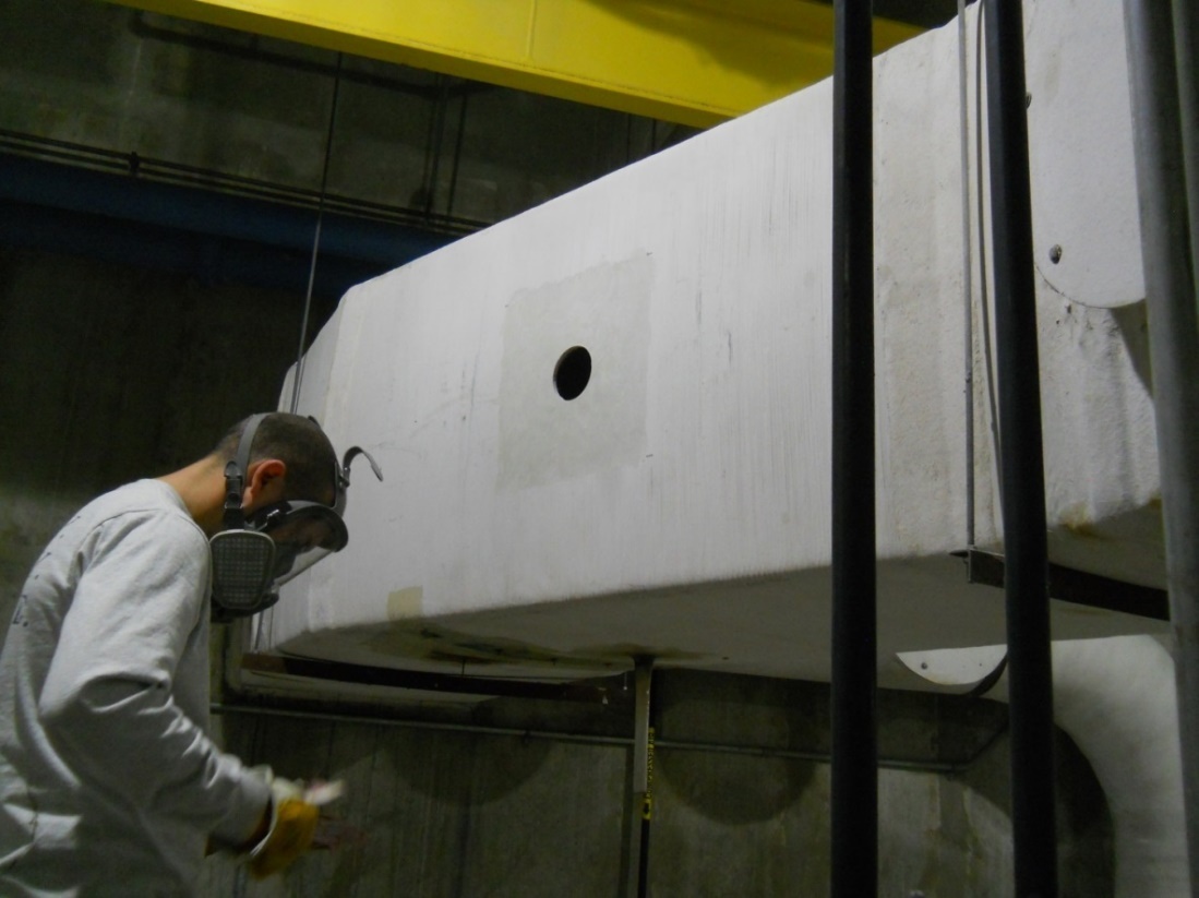
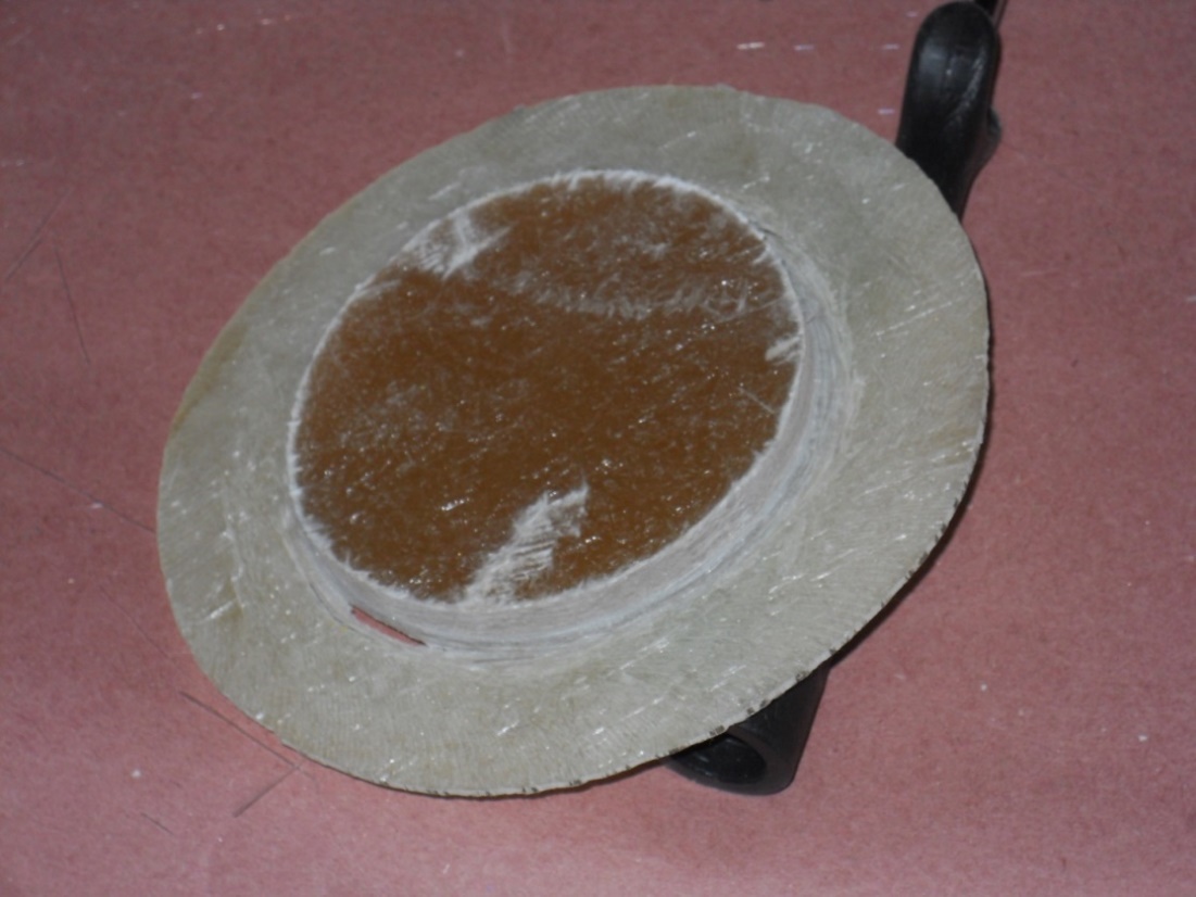
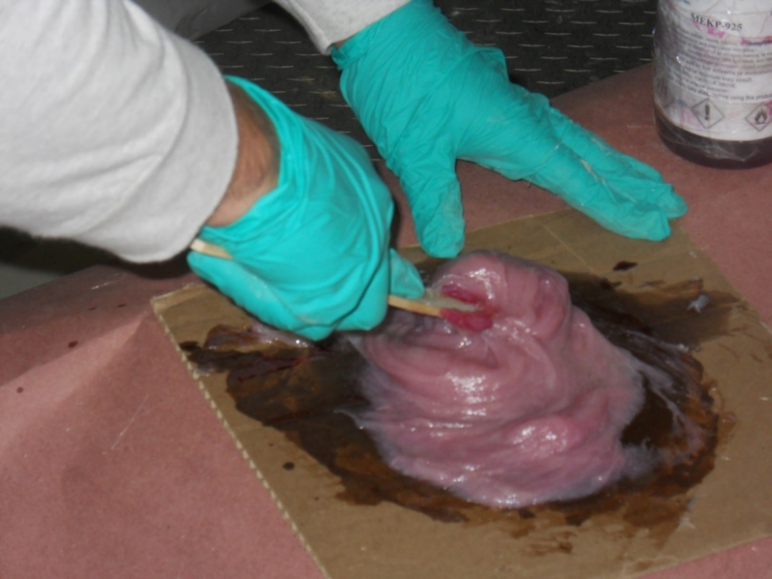
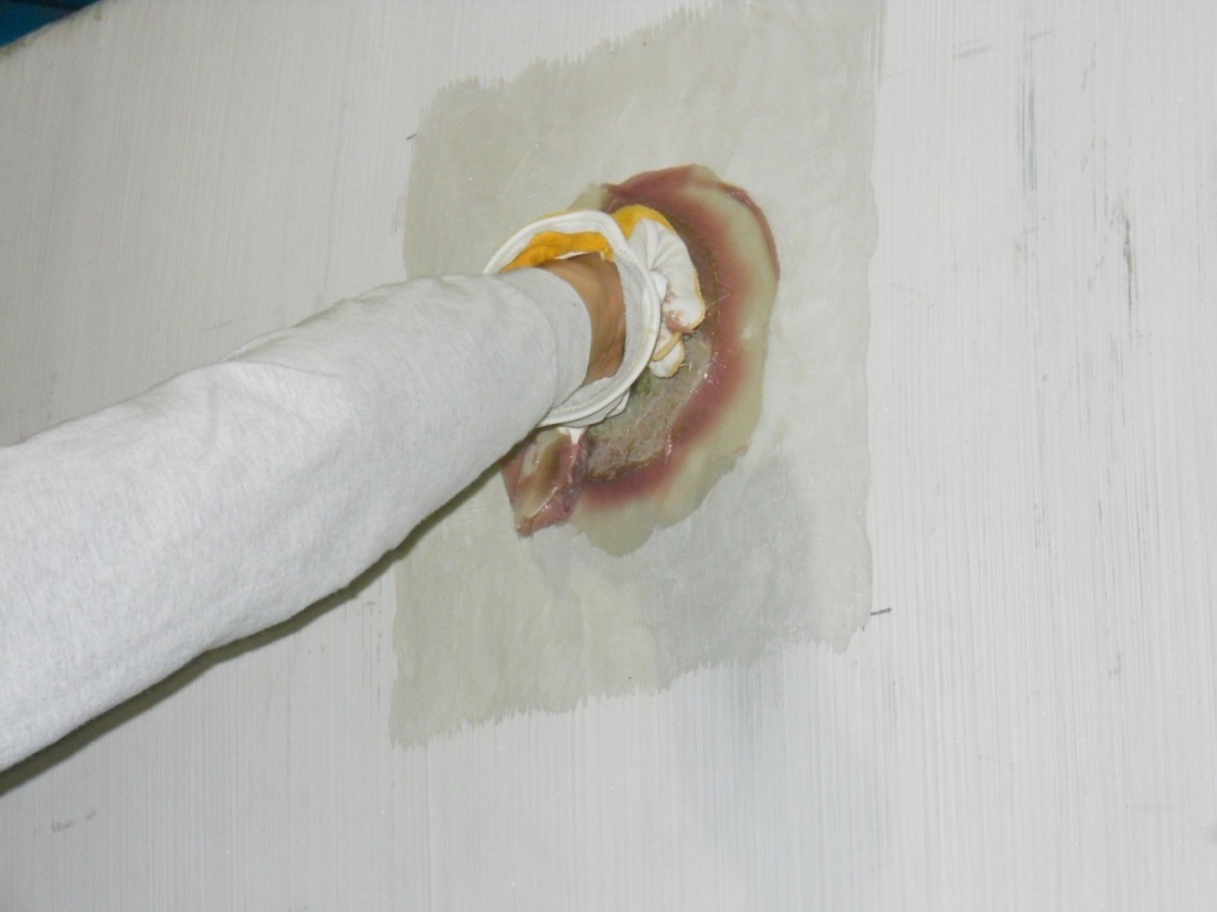
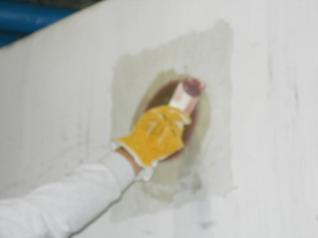
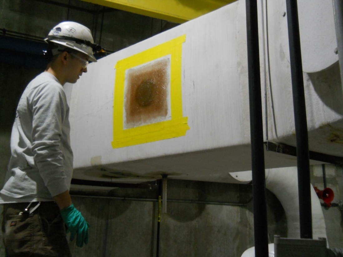
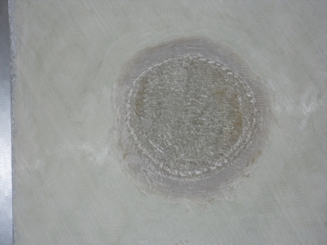
General Condition Assessment. For general condition assessment purposes, samples of the FRP can be removed by core drilling or cutting through the FRP laminate. This should be done only where evidence of defects or attack has been identified. Sampling can be effectively performed with odor control equipment on-line or off-line depending upon specific plant operating conditions, using the methods depicted in Photos 2 through 9. Scrubbers and absorbers need to be off-line for this sampling. Ductwork can often be sampled at lower fan airflow velocities without full shutdown. The removed core samples can be sized according to the test needs. For example, a 6-inch core can be used for laminate glass content and sequence, while an 18-inch core is needed for physical strength testing of the laminate.
Coupon sampling also is a key way to measure and assure that FRP laminate thickness requirements for the equipment are met.
Material Selection. To confirm the proper resin material was used in the FRP, removed samples of the FRP can be analyzed by FT-IR to compare the chemical composition spectrum with the known FT-IR spectrum for the specified resin. Figure 3 above shows a typical FT-IR comparison.
Again, visual evidence of FRP degradation may lead one to perform this sampling and testing at failed and non-failed locations for comparison purposes.
Proper Cure or Resin Degradation. To check that the resin properly cured or has not degraded, visual inspection and physical probing with a knife or scraper are first recommended. If obvious softening is not indicated in this way, Barcol hardness testing, as described above, can be performed on removed coupons to discern if the FRP has lost hardness and did not initially cure properly.
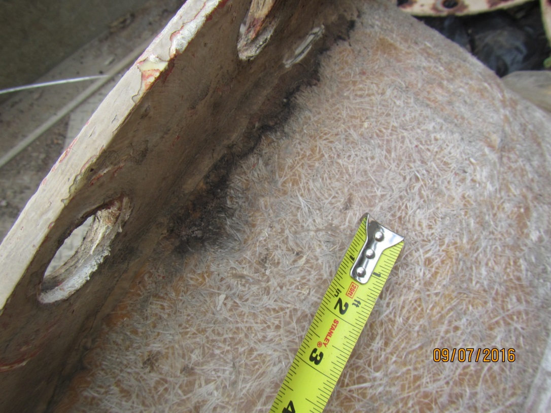
Mechanical Damage. This is primarily detected by visual examination of both the inside and outside surfaces of the ductwork or equipment. Look for the tell-tales described earlier in this paper—such as cracking or impact damage—and document those indications with digital photographs and written descriptions (Refer to Photo 10).
Environmental Defects. These defects, which mostly involve UV degradation of the resin and ultimate fiber reinforcement exposure, are detected visually. Photo 11 shows a typical case of UV degradation.
Fabrication Defects. To check for fabrication defects—assuming visual inspection has shown evidence of cracking, crazing, deflection, or laminate delamination—coupons should be removed and tested for resin-to-reinforcement ratio (glass content) and for laminate sequence. These examinations are performed in accordance with ASTM D2584, Standard Test Method for Ignition Loss of Cured Reinforced Resins. The resin is burned off and what is left is the glass reinforcement. From this test, the resin content can be checked on a percentage basis to determine compliance with the specifications and pertinent standards. In addition, the laminate sequence can be laid out to assess if all laminate layers and reinforcement types (i.e., WR, CSM, etc.) were actually used in the fabrication as specified and designed.
Refer to Figures 4 and 5, which show laminate sequence evaluation for two coupon samples from odor control ductwork at two different odor control facilities.
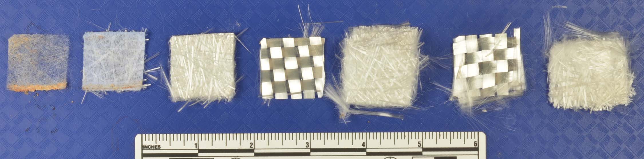
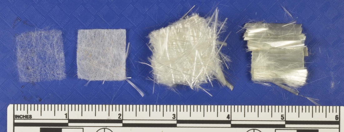
The laminate sequence analyses shown in Figure 4 revealed double resin-rich veils, which exceeded the 20-mil minimum thickness required by the project specifications. The laminate sequence analyses shown in Figure 5 also revealed double resin-rich veils, which exceeded the 20-mil minimum thickness requested by the project specifications; however, one CSM layer was missing, per the design, which was also reflected in the laminate thickness measurement.
From the Loss-on-Ignition tests, the resin content percentages for the laminates can also be checked and compared to specified values.
Many other fabrication defects can occur in FRP equipment. Experience is essential in knowing what else to look for.
Secondary Laminations or Joint Problems. As discussed above, joint preparation, cleaning, and hand lay-up practices are of critical importance to assuring leak-free joints that provide a continuous process barrier and prevent process contamination of the structural laminate wall.
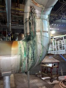
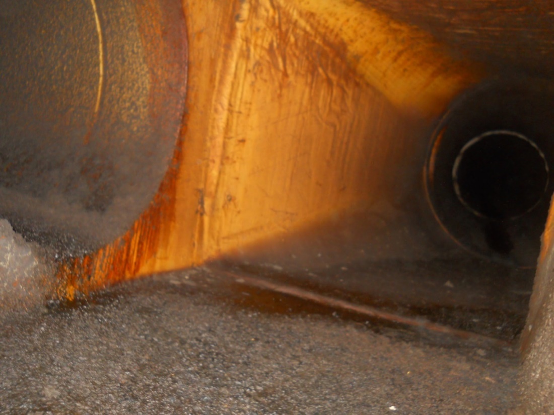
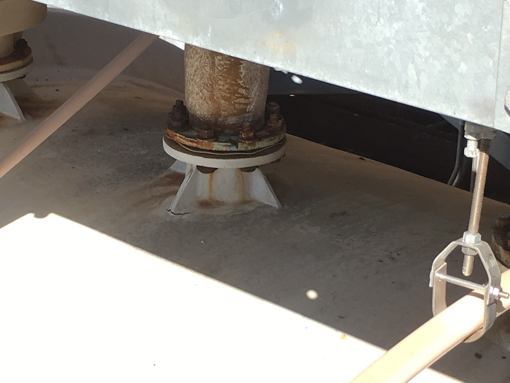
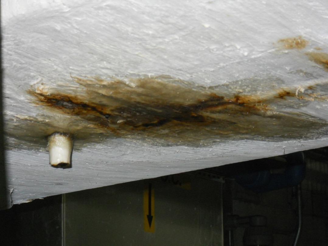
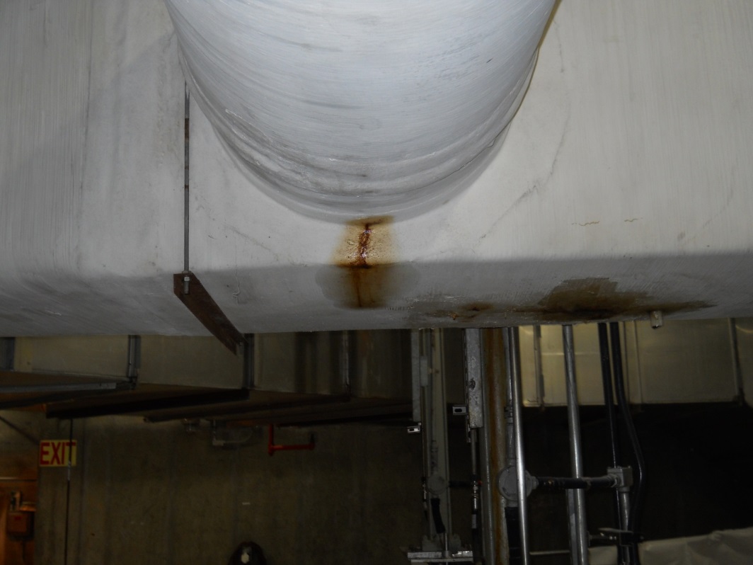
Leakage of process fluids are dead giveaways that either the corrosion barrier has been compromised or joining quality was poor. Notice the leakage of carry-over of wastewater condensation and biogenic-formed sulfuric acid through the ductwork structures in Photos 12 and 13. All of the leakage in Photo 13 emanated from a poorly made butt joint.
Understanding how FRP odor control ductwork and equipment is fabricated and how it can degrade or otherwise fail due to built-in defects is a prerequisite for knowing where and how to look and assess its in-service condition. This paper has hopefully provided some insight to wastewater engineers and operators as to how best to have condition assessments performed on these important assets.