
When establishing the minimum conditions suitable for coating concrete, many coating manufacturers, and hence specifying engineers and contractors, generally rely on unrealistic moisture content and moisture vapor emission rate requirements. These compulsory values are founded on laboratory testing rather than field experience, or worse still, on supposition rooted in unachievable and unrelated requisites. This paper presents a discussion on the repeatability problems and margin of error concerns intrinsic to the most widely specified moisture related test standards especially when used for below grade structures. The author will further describe case histories which demonstrate the inaccuracy and unsubstantiated reliance on these commonly used test methods. These examples will be used to illustrate the many variables which influence moisture content and vapor emission rates and how the test results can be misleading. Successful coating performance and coating failures will be shown when the specified test requirements could not be achieved or were met respectively. The paper will close with some recommendations which establish some practical criterion for deciding when and where not to coat concrete. The criteria proposed will include moisture testing value ranges, trends in the test data as well as consideration of the conditions to which the coated substrate will be exposed.
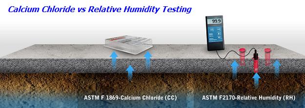
The most commonly specified quantitative moisture related test standards for coating concrete are ASTM F1869 and ASTM F2170. These standards are routinely listed in product data sheets and specifications without any qualification as to the type of structure to be coated. Floor slabs on grade within office buildings are treated exactly the same as below grade wet wells in wastewater pump stations. For each standard, manufacturers and engineers have generally adopted threshold values for deeming concrete suitable to be coated. For ASTM F1869, the target value is less than 3.0 lbs. of moisture per 1,000 sq. ft. in 24 hours. This establishes a moisture vapor emission rate. For ASTM F2170, the generally accepted maximum relative humidity for concrete is 80%. This paper intends to demonstrate that these threshold values are either unachievable or unrealistic when one is determining whether or not a below grade concrete structure should be coated. In addition, this paper will recommend more pragmatic ways to specify moisture related requirements to ensure successful concrete coating applications in wastewater structures. But first let’s address applicability, repeatability, and margin of error concerns for these prevalently used test methods.
The maximum prescribed values for relative humidity and moisture vapor emission rates (MVE rates) are based on either controlled conditions or unrelated requisites. Specifically, recommended relative humidity minimums were selected based on laboratory testing or controlled conditions for indoor flooring installations. Acceptable MVE rates were chosen because resilient sheet flooring manufacturers used an empirically established threshold. That 3.0 lb. of moisture per 1,000 sq. ft. per 24 hour target (or less) is acceptable for resilient sheet floor covering materials which are installed using adhesives on concrete floors. The coatings industry has blindly accepted this threshold with no real supportive data base.
The MVE rate test method was developed specifically for bare concrete floor slabs. The calcium chloride test, as it is often called, should be conducted “under the same temperatures and humidity conditions expected during normal use” for the space to be coated. When this is not possible, ASTM F1869 specifically prescribes the following conditions: 75+ 10oF and 50+ 10% R.H.1 This means 65o to 85oF and 40 to 60% R.H. These are conditions which are maintained in buildings not in below grade pipe galleries, concrete channels or tanks. Most of the structures that require protective coatings in wastewater applications are at least partially, if not fully, below grade. In these structures, the concrete tends to assume the temperature of the ground which is typically 50oF + 5oF throughout North America. Additionally, most of these collection system or treatment plant structures are influenced by exposure to either static or fluctuating ground water levels. This requires the structure to be heated to reach the temperature range specified in ASTM F1869. When heated, the soil side and the air side of the concrete will have very different relative humidities. Furthermore, the normal use of these structures will involve immersion service or unheated and unventilated high humidity headspace environments. Neither scenario provides conditions similar to those under which the tests will be performed. It is clear that the 3 lbs. of moisture threshold value is not based on empirical coating adhesion, cure, or performance data. And it is a fact that any one test result is a snapshot in time affected by conditions which are not likely under normal future exposure. Given this knowledge, the efficacy of the 3 lbs. threshold is questionable in any application for coatings on concrete. To a slightly lesser extent, reliance on the applicability of the ASTM F1869 test method for below grade structures is also dubious.
ASTM F2170 is entitled, Determining Relative Humidity in Concrete Floor Slabs Using In-Situ Probes. Again, this test was developed specifically for concrete floor slabs and not concrete walls or overhead slabs. This test standard states that the test shall be conducted at “the average ambient air temperature and relative humidity typically found in occupied spaces during normal use.”2 These requirements make little sense for below grade concrete structures which will rarely be occupied spaces. Therefore, neither temperature nor humidity will be normally controlled within these structures. Again in wastewater applications, most of these concrete spaces will be exposed to immersion or uncontrolled ambient air conditions. Moreover, the lion’s share of the surfaces to be coated are not floor slabs, but rather walls and overheads. Further, headspaces are more often than not more corrosive in wastewater exposures than immersed concrete. So the applicability of the relative humidity (R.H.) test for determining if a below grade concrete structure is ready to coat is suspect. For many coating manufacturers and engineers, the generally accepted maximum R.H. value for coating concrete is 80%. This author has found this target almost impossible to hit in most subgrade structures. With new concrete where the probe’s liners were placed in the fresh concrete and in existing concrete (where the holes were drilled), the 80% R.H. range has been very difficult to achieve in a reasonable timeframe (4 to 6 weeks). In existing non-waterproofed concrete structures exposed to high external ground water levels, reaching R.H. values below 85% has been rare (at probe test depths of 40% of concrete thickness).
Because ASTM F2170 was developed for floor slabs to be tested under controlled temperature and humidity conditions expected during normal use, the suitability of this test method for below grade structures is questionable. And given the widespread difficulty of achieving 80% or less R.H. values using this method for non-occupied spaces, one must question the applicability of the 80% R.H. threshold for coating subgrade structures.
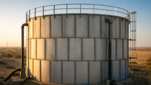
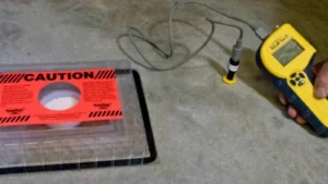
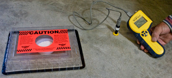
Photo No. 1 shows the test set-up for both ASTM F1869 and ASTM F2170.
The language in ASTM F1869 is crystal clear on the limitations of the test data. The MVE rate for a given test will “reflect the condition of the concrete floor at the time of the test and may not indicate future conditions.”3 By its very language, this test method presents repeatability challenges. For instance, the standard requires that the test site be at “the same temperature and humidity expected during normal use”. This is almost always impossible to achieve in a below grade structure during construction. If it involves a subgrade pipe gallery that will be heated during normal use, it will not be similarly heated during construction. If the structure to be coated is a buried wet well that will see immersion service normally, how does the calcium chloride test have any bearing on the effects of high or low moisture vapor emission rates?
This test method requires the complete sealing of a transparent plastic cover to an irregular concrete surfaces using a strip of pliable sealant. If this seal is not air tight, the results of the test are erroneous.
This test method is designed to be used on floor slabs and there is no provision in the standard (no practical way) for performing this test on vertical surfaces or overhead surfaces. This renders the use of this standard at best difficult for anything other than a flooring application.
The movement of moisture vapor is “a natural process driven by environmental conditions”.4 That is correctly stated in ASTM F1869. It is well known that large disparities in temperature and humidity across a concrete floor slab or wall (soil side to unburied side) drive moisture vapor emission rates. So if the relative humidity of the soil on one side of a concrete wall and the relative humidity of the tank side of the wall are both 100%, what will drive the MVE rate? And if the test is performed when the structure is heated and the test value is above the magic 3 lb. limit, won’t the MVE rate drop once that structure is filled with water? Or if the heat is turned off and the test is repeated, will the result be repeatable? It probably will not be. Here are some real world examples of the use of ASTM F1869:
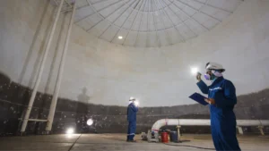
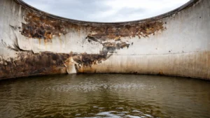
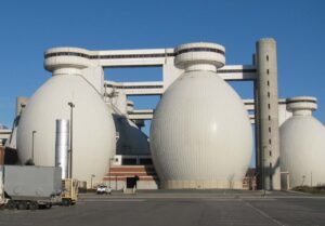
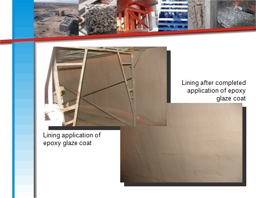
MVE rate tests were performed on the floor of a new below grade concrete channel. The influent channel will convey wastewater flow to primary clarifiers in the future. The test results were all greater than 3 lbs. per 1,000 sq. ft. per 24 hrs. Multiple sets of tests were performed with results in excess of 5.0 and 6.0 lbs. per 1,000 sq. ft. per 24 hrs. This work was performed during a cooler time of the year so the channel was being heated. The project schedule mandated that the coating work be completed and the channel be placed into service. Approximately two years later, the channel was dewatered and inspected. No blisters or other moisture related deficiencies were observed. Photograph No. 2 shows this coated channel at a wastewater treatment plant.
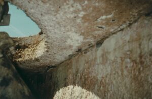
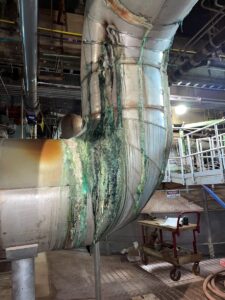
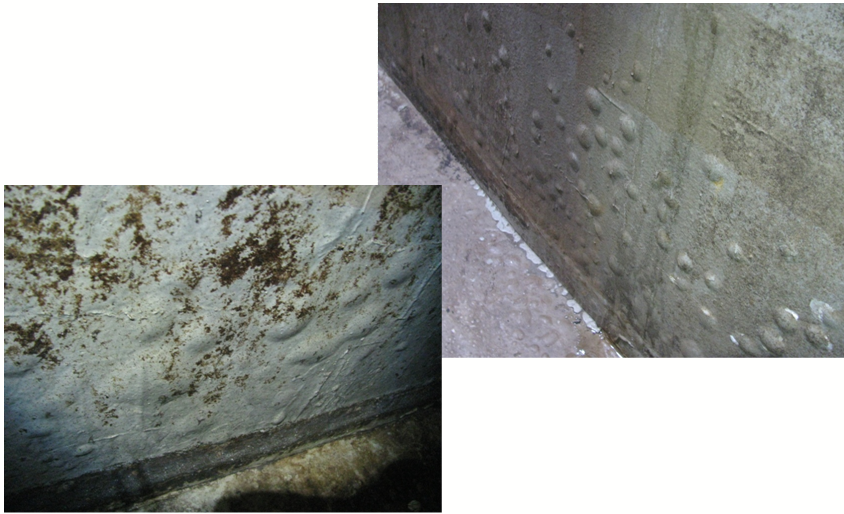
Calcium chloride test kits were used to measure MVE rates on the wall surfaces of a new concrete pipe gallery. The gallery walls were common to tanks on either side which were in service at the time of the testing. The test values were all reported to be between 2.5 and 3.0 lbs. of moisture per 1,000 sq. ft. per 24 hrs. The test kits were carefully sealed to the walls and held in place with wooden supports. The gallery walls were prepared and coated. Within about one year, widespread liquid filled blisters appears in the gallery wall coatings. Photo No. 3 shows these blisters. The pipe gallery is not heated, but it is ventilated. The ventilation was activated several months following the coating application work.
These actual examples demonstrate that the margin of error for these tests can be substantial if we follow the 3 lbs. threshold. The physical implementation, particularly the air tightness requirement for the cover and the vertical surface application difficulties, further bring into question the reliability of this test method.
We must also address the moisture vapor retarder aspect of this test method. While it is presented as non-mandatory information, the language in the standard’s appendix part XI is quite clear: “A moisture test indicates a condition of the concrete floor slab at the time of the test, under the ambient conditions of the test, and may not predict the future moisture condition of the floor slab. This is especially true if an effective moisture vapor retarder is not present or has been comprised by damage or improper installation.”5 It is rare for an effective moisture vapor retarder to be present on the soil side of all the surfaces of a below grade concrete structure. So again there are considerable margin of error and repeatability concerns with the use of this test for determining whether or not and when to coat concrete. Furthermore, actual field experience suggests that reliance on the 3 lb. threshold value is an unrealistic and unsubstantiated objective for coatings on concrete.
The Relative Humidity test as delineated in ASTM F2170 has notable qualifications with respect to its applicability to below grade concrete structures. As previously mentioned, it requires that the test be performed at the “average air temperature and R.H. typically found in occupied spaces during normal use.” Most buried or partially subgrade concrete structures in wastewater facilities are not or do not become occupied spaces. Most are filled with wastewater and some share common walls with liquid filled tanks. So like ASTM F1869, the relative humidity testing using in-situ probes has significant repeatability issues simply based on the expected change in conditions from construction exposure to normal use. This is because of both changing conditions and the presence or lack of moisture vapor retarders or external waterproofing. As ASTM F2170 states, “moisture permeating from concrete floor slabs affects the performance of flooring systems such as resilient and textile floor coverings and coatings.”6 The amount of moisture vapor permeating from a concrete slab must be influenced by the amount of moisture vapor passing through the slab from the soil-side or water side. Therefore, the lack or presence of a moisture vapor retarder or waterproofing coating on the exterior side of the concrete must make the relative humidity test results vary. Many existing below grade concrete structures were not waterproofed. It is not typical for new buried structures to be waterproofed unless there will be common spaces which are designed to be dry.
Whether Procedure A for hardened concrete or Procedure B for fresh concrete is utilized, ASTM F2170 requires that the probes be calibrated regularly using precise procedures. Improper calibration can significantly affect the test results. For either test procedure, the concrete floor slab is also required to be conditioned. The standard specifically requires that the “floor slabs shall be at service temperature and the occupied space above the floor slab shall be at service temperature and service relative humidity for at least 48 hours before making relative humidity measurements in the concrete slab”.7 Even if this equilibration exercise is accomplished, those conditions are unlikely to prevail under normal use in a below grade structure. Once again, these facts point to repeatability and margin of error concerns for this test method.
Section 10.2 of ASTM F2170 presents how the depth for probe holes is determined using a table. That table differentiates between slab drying from one side (top only) or both sides (as in elevated slabs not in metal deck) with 40% and 20% drill-depths respectively. The standard then notes that, “testing at these depths will indicate the potential equilibrium relative humidity that will be established within the concrete slab after a low-permeability floor covering is applied.” The basis for these determinations is not presented in the standard. Moreover, this statement makes the assumption that the moisture content in a slab is uniformly distributed and that simply isn’t ever the case. This point again highlights margin of error concerns with this test method.
Coating manufactures and many engineers have adopted the threshold maximum value of 80% R.H. as a guideline for determining the coatability of concrete. This value is very difficult to achieve in new concrete structures which have been waterproofed let alone for those which have not. It is also hard to get below 80% R.H. values in existing structures for which the quality of waterproofing cannot be ascertained. As an example, a new concrete wet well structure was constructed. Probe holes were formed at 40% depth in the wet well floor and lower wall elevations. The probes were inserted after the concrete cured for over 160 days. The concrete surface temperature and the air temperature and humidity conditions above the test probes in the structure were measured. The air was at 62oF and 50% R.H. The surface temperature of the concrete was 54oF. The actual service conditions will be 100% R.H. (immersed or in the headspace over the liquid level) and the temperature will vary between about 55 and 75oF. These tests can’t be run at the actual service temperatures expected in most below grade concrete structures. The R.H. measurements for the concrete were taken at the conditions reported above on two consecutive weeks and gave the following results:
| Test Location | R.H. Values
Week 1 |
R.H. Values
Week 2 |
| Floor – Test 1 | 90% | 94% |
| Floor – Test 2 | 89% | 81% |
| Wall – Test 1 | 92% | 88% |
| Wall – Test 2 | 88% | 85% |
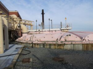
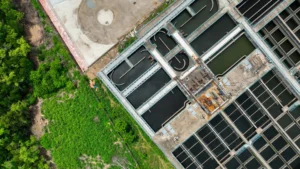
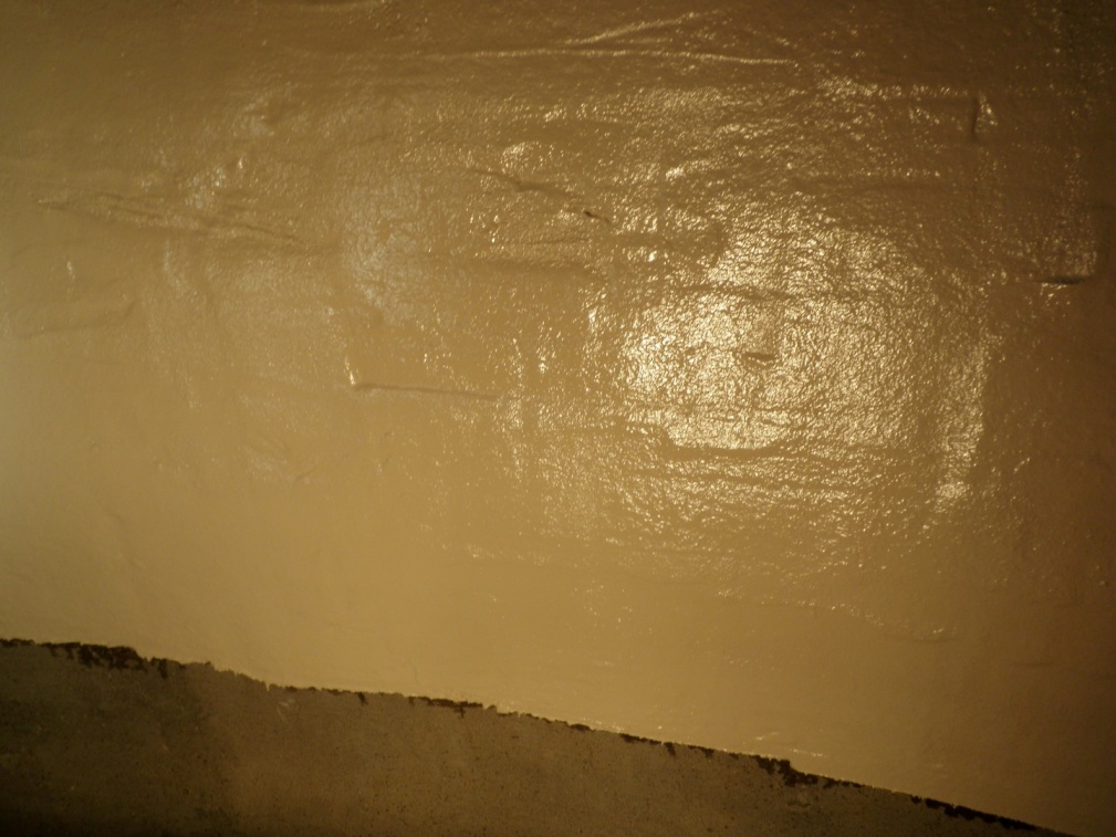
The coating work was delayed for another month on this project and still the R.H. threshold of 80% or less could not be achieved. The coating system was installed. Reinspection of the structure two and one-half years later showed no evidence of moisture related coating failures. Photograph No. 4 shows the coating application work in this pump station wet well.
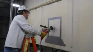
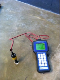
Even in existing wastewater structures, reaching the 80% R.H. plateau has been problematic. For example, an existing concrete wet well needed to be resurfaced and coated. R.H. probes were installed at 40% slab depth following ASTM F2170. Initial test values were all well above 85% R.H. After nearly one month of heating and forced ventilation in the structure, the R.H. values were still above 80%. However, the trend in the data was consistently downward after four sets of measurements at four locations were made. The decision to coat was made despite the higher than acceptable R.H. values specified. The coating work was carefully inspected after two (2) years of service and no moisture related coating problems were observed. Photograph No. 5 shows a typical R.H. probe installation.
The accuracy of this test method is influenced by too many variables for a fixed R.H. threshold value to be reliable. The precision and bias section (12.0) of standard ASTM F2170 even points this out. It states that “the precision of this test method is being determined”. Under 12.2, the bias of the test method is described as being “affected by the accuracy of probe calibration and can be strongly affected by equilibration of probes in the concrete”.
This author believes that there is significant merit to the continued reliance on use of the Plastic Sheet Test Method (ASTM D4263) for moisture testing when making the determination to coat concrete or not. While this test method is purely qualitative and can be affected by a number of variables, experience has shown it to provide a valuable go – no-go determinant for coating concrete. Given that this standard does not require surface or ambient air conditions at the test site to be the same as the normal in-use conditions, it is a much more versatile test method than the quantitative methods discussed above.
ASTM D4263, the Standard Test Method for Indicating Moisture in Concrete by the Plastic Sheet Method, is used to indicate the presence of capillary moisture in concrete.8 It is within its simplicity that one finds this standard’s greatest value. It must be conducted when “the surface temperature and the ambient air conditions are within the established parameters for application of the coating system”. These conditions can be controlled. So if moisture is present on the back of the polyethylene sheet, too much capillary moisture is present and the coating should not be applied. Once can argue that many factors can influence the collection of moisture on the back of the sheet. The sheet must be sealed completely to the concrete at all edges. If air with a higher R.H. than the upper surface of the concrete gets under the sheet, moisture can collect on the backside of the sheet. But if this occurs, it is also likely that the minimum air and surface conditions are not within the coating manufacturer’s established parameters for coating application. This reinforces the need to maintain those minimum requirements for temperature and R.H. for the 16 hours prescribed by the test method prior to examining the underside of the sheet and the concrete surface for the presence of moisture.
The Plastic Sheet Method is far from perfect, but it is a valuable tool for indicating the presence of capillary moisture near the surface. It does not necessarily detect high R.H. in the concrete. This is because under controlled coating-acceptable conditions, there is lots of surface drying area around the plastic sheet patch. If there is a sustainable source of moisture on the soil-side of a concrete floor slab or wall and if the conditions which drive moisture vapor transfer are present, high MVE rates are likely. And the Plastic Sheet test is not designed to indicate high moisture vapor emissions. However, if the minimum temperature and R.H. for a given coating system are provided within a structure, it is likely that those conditions will drive moisture vapor transfer through the concrete toward the warmer, less humid space. This means the moisture is more likely to collect on the plastic sheet if there is high vapor drive present.
From the pragmatic perspective, experience has shown the Plastic Sheet test to be effective when used alone or in concert with careful use of the quantitative test methods. For instance, when R.H. values (Using ASTM F2170) have trended downward over time (but not reached 80%) and Plastic Sheet tests have indicated no presence of moisture, coating performance has been routinely successful in below grade structures. Similarly where calcium chloride test results were above the 3 lbs. threshold level (as high as 6.0 lbs./1,000 sq. ft. 24 hrs.) and the Plastic Sheet test results were negative, coating application has been performed with no subsequent formation of moisture related deficiencies in below grade structures commonly filled with water or wastewater when in service.
Based on the technical discussion provided and the experiences shared above, the following pragmatic recommendations are made when determining whether or not to coat concrete in below grade structures:
A. Only use the calcium chloride test for MVE rate testing for structures which will be heated or cooled and ventilated for personnel access in the future and will be waterproofed externally. This includes basements or pipe galleries or other spaces which will have common walls with soil or water/wastewater retaining structures. In such structures, the conditions found under normal use of the space can be provided making the test results valid and useful. This test method is best suited for floor slabs. Should these tests be performed on vertical surfaces, great care must be exercised to assure the transparent cover is well sealed and supported. In addition, the calcium chloride container must be kept in position to avoid spilling or tipping. Where ASTM F1869 is utilized, consult with the selected coating manufacturer to determine the right MVE rate threshold. Several coating manufacturers have determined more realistic MVE rate levels for specific coating products. (Above the arbitrary 3 lb. limit). If the structures were not or will not be externally waterproofed (when placed in service) or external waterproofing measures can’t be affirmed (in the case of existing structures), do not use MVE rate testing in accordance with ASTM F1869. With no moisture vapor retarder or barrier present, the results of the tests will not be valid for in-service conditions. In these instances, rely on a combination of the Plastic Sheet test and the R.H. test (ASTM F2170) as outlined below. If the structure to be coated is a tank or channel or chamber which will normally be exposed to immersion service, rely on the Plastic Sheet test or the Plastic Sheet test performed in concert with R.H. testing where a downward trend in R.H. can be documented. Experience suggests that a maximum R.H. average range of 86 to 88% at mid-slab or wall depth for the probes and a negative Plastic Sheet test gives a successful result in most cases. The downward trend of the R.H. values must be based on three (3) data points for at least 4 test sites within the structure over at least a three (3) week period.
B. Recommend that external waterproofing be used on all below grade water retaining structures (floors and walls) which are expected to be coated or lined internally. This should be achieved with sheet moisture vapor retarders or barriers for floor slabs and with either sheet waterproofing or liquid applied coatings for walls. This recommendation should find its way into specifications whenever and wherever possible.
C. In below grade wastewater structures, do not recommend coating the concrete more than a few feet below the normal operating level. Municipal wastewater is generally not corrosive to concrete or reinforcing steel for immersion exposure unless chloride concentrations in the wastewater are too high. This also provides additional unsealed concrete surfaces through which moisture vapor can escape. Another exception to this recommendation involves those structures where abrasive erosive conditions will prevail. Examples would include grit removal chambers or structures which need to be coated with robust reinforced coating systems.
D. If the average ambient air temperature and R.H. typically expected in the spaces of a structure during normal use cannot be achieved during the test timeframe (including conditioning of the concrete to the service temperature), there is no point in attempting to test for concrete R.H. in accordance with ASTM F2170. Under such circumstances, the Plastic Sheet test should be relied upon provided certain conditions. Those conditions would include the following:
1. Do not coat concrete which has not been externally waterproofed where high ground water levels or fluctuating ground water levels are known to be present relative to the structure.
2. If the headspaces (under normal service conditions) need to be coated, but not the lower walls and floor of the structure, reliance on the Plastic Sheet test results will be acceptable provided the external surfaces of the headspaces have been waterproofed.
E. For a new concrete structure which is known to be externally waterproofed and in which conditions can be controlled to meet the normal use temperature and R.H., a downward trend in R.H. values should be considered more important than the target R.H. value. This would include the requirement for the 48 hour conditioning of the concrete temperature. Under these conditions, it is recommended that a downward trend in R.H. values in concert with a negative Plastic Sheet test result would be acceptable for coating concrete. The recommended declining trend would have the following requirements:
• Maximum average R.H. value range of 86 to 88% based on at least 4 test sites.
• Downward trend with consecutive decline in R.H. values over three (3) data points in three (3) weeks for a minimum of four (4) test sites per structure.
The recommendations made here are not meant to apply universally to all below grade concrete structures. The actual field conditions during construction and the expected in-service exposures need to be carefully considered on a case by case basis. But it is this author’s hope that the information presented will be helpful to the coatings industry from a guideline perspective.
1. ASTM F1869-11 Standard Test Method for Measuring Moisture Vapor Emission Rate of Concrete Subfloor Using Anhydrous Calcium Chloride – 6. Conditioning, paragraph 6.1, page 2.
2. ASTM F2170-11 Standard Test Method for Determining Relative Humidity in Concrete Floor Slabs Using in situ Probes – 3. Terminology, paragraph 3.1.2, page 1.
3. ASTM F1869-11 Standard Test Method for Measuring Moisture Vapor Emission Rate of Concrete Subfloor Using Anhydrous Calcium Chloride – 4. Significance and Use, paragraph 4.1, page 1.
4. ASTM F1869-11 Standard Test Method for Measuring Moisture Vapor Emission Rate of Concrete Subfloor Using Anhydrous Calcium Chloride – 4. Significance and Use, paragraph 4.1, page 1.
5. ASTM F1869-11 Standard Test Method for Measuring Moisture Vapor Emission Rate of Concrete Subfloor Using Anhydrous Calcium Chloride – Appendix X1. Moisture Vapor Retarders, paragraph X1.2, page 4.
6. ASTM F2170-11 Standard Test Method for Determining Relative Humidity in Concrete Floor Slabs Using in situ Probes – 5. Significance and Use, paragraph 5.1, page 1.
7. ASTM F2170-11 Standard Test Method for Determining Relative Humidity in Concrete Floor Slabs Using in situ Probes – 9. Conditioning, paragraph 9.1, page 3.
8. ASTM D4263-83 (Reapproved 2005) Standard Test Method for Indicating Moisture in Concrete by the Plastic Sheet Method – 1. Scope, paragraph 1.1, page 1.