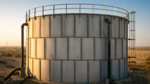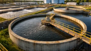


Wastewater treatment plant clarifier environments present challenges for selecting materials of construction. Coated carbon steel, hot-dip galvanized steel, and stainless steel are most commonly specified for new or refurbished clarifier mechanisms, and all have their advantages and disadvantages with regard to achieving the intended design life. This presentation discusses the corrosive conditions in primary and secondary clarifiers; how various process conditions can affect the corrosion mechanisms; in what situations each of these construction materials is or is not appropriate; and how fabrication quality and other details can affect corrosion resistance. Also discussed are the detrimental electrochemical effects of using combinations of these materials, and how those effects can be minimized. Examples will be presented from clarifiers in Texas, Nevada, and New England.
Clarifier mechanisms have historically been fabricated from steel, utilizing a protective coating system in an attempt to prevent corrosion. Technological advances have resulted in coatings that last longer and require less maintenance. In recent years, hot-dip galvanized coatings have competed with more traditional, organic coatings. Even more current is the move to stainless steels, including austenitic (e.g., 304, 316) and duplex (e.g., 2205) alloys.
Each of these materials has advantages and disadvantages when it comes to performance, maintainability and life-cycle cost. Navigating these differences, along with comprehending the variability in clarifier environments, can make materials selection quite complicated. Studying the corrosion mechanisms and root causes of numerous failed or severely corroded clarifier mechanisms has revealed several guidelines that should be understood and utilized by design engineers involved in new or rehabilitation design.
The first step is comprehension of material-environment interactions, and how changes in either of them—sometimes even subtle changes—can have major consequences.
Corrosion of carbon steel immersed in wastewater clarifiers is mainly oxygen-driven, so corrosion rates are largely determined by how much oxygen (O2) gets to the surface of the metal. In general, aerated wastewater is only mildly oxidizing and, with wastewater temperatures rarely exceeding 100°F (35°C), oxygen-driven corrosion of bare steel is fairly slow, generally less than 0.01 inch per year (10 mpy). Some treatment plant processes generate higher dissolved O2 levels in the wastewater, such as pure oxygen treatment. [1] In these cases, carbon steel corrosion rates can be higher. Stainless steels generally do not corrode in such aerated, aqueous conditions at near-neutral pH, unless other conditions promote problems.
Where aeration is not assured, especially under deposits and in stagnant conditions, acidic environments can form, often containing sulfide and other aggressive ions. In such conditions, microbiological reactions can create micro-environments corrosive to carbon steel and sometimes also to stainless steel. From a corrosion point of view, the most important types of bacteria in wastewater are those that metabolize sulfur compounds to produce acidic conditions that are corrosive to carbon steel and stainless steel. Some other bacteria oxidize ferrous ions to ferric ions, which makes the local environment more corrosive to carbon steel as well.
Differential aeration effects influence corrosion in wastewater treatment clarifiers. Aggressive cells can be established between the rake arm surfaces within the sludge layer and those rake arm surfaces above the sludge. The surfaces in the sludge corrode faster than the surfaces above the sludge because of differential aeration and/or concentration effects. These effects increase the open circuit potential difference between the two regions, one cathodic (passive) and the other anodic (active). “Potential” is the term used to describe the electromotive voltage of the metal at anodic or cathodic sites.
The pH of domestic wastewater normally is 6 to 8, running slightly on the alkaline side of neutral where there is higher use of soaps and household cleansing materials. Corrosion rates for steel tend to increase with decreasing pH. Dissolved carbon dioxide (CO2) concentrations in wastewaters can depress pH, especially where covered tanks do not allow the CO2 to dissipate into the air, but rather remain dissolved as carbonic acid. This is common in pure oxygen reactors upstream of secondary clarifiers. A great deal of CO2 also evolves from the bacterial metabolism of organic compounds during secondary biological treatment. Experience shows that dissolved CO2 concentration has a greater impact on the corrosion of zinc, as discussed below, than of bare carbon steel.
The electrolyte is very conductive in both the primary and secondary stages of treatment. This conductivity increases with high dissolved chloride, sulfate, and sulfide concentrations. Accordingly, wastewater treatment plants served by collection systems with greater coastal infiltration can suffer higher metal corrosion rates. Also, treatment plants that use more ferric chloride for promoting flocculation in the clarifiers, or for reducing dissolved hydrogen sulfide (H2S) concentrations upstream of the clarifiers, will tend to have higher carbon steel and stainless steel corrosion rates.
Corrosion rates for submerged steel tend to be greater at higher elevations in the wastewater, where dissolved O2 contents are greater. Corrosion rates also increase with radial distance from the center of the clarifier, as the relative velocity between the rake arm and water increases. For example, an increase in velocity from 0 to 0.25 feet per second—which can occur between the center column and the tip of the rake mechanism—can double the corrosion rate of bare steel. Increasing velocities affect the ability of protective scales to form and remain adhered to the steel surface.
The major difference in corrosion mechanisms between primary and secondary clarifiers involves biogenic sulfide corrosion. This is a gas phase or vapor-phase corrosion problem whereby sulfuric acid is formed through the biogenesis of H2S by sulfur oxidizing bacteria. This occurs in the aerated headspaces of covered primary clarifiers. Biogenic sulfide corrosion causes rapid corrosion rates of bare carbon steel in these clarifier headspaces.
By the time the wastewater reaches aeration or pure oxygen exposure in the secondary stage of treatment, the reducible H2S and other sulfur species are largely gone or have been reduced substantially upstream of the secondary clarifiers. In secondary clarifiers, the corrosion mechanisms above the waterline generally are oxygen-driven and influenced by weathering exposure and high humidity from the evaporative vapors from the wastewater.
Most of the information presented above is with regard to the corrosion of bare carbon steel, which is not typically found in clarifiers, except where protective coatings have failed. Discussed below are organic and hot-dip galvanized coatings, along with solid stainless steel as alternatives to uncoated carbon steel.
Coated Carbon Steel
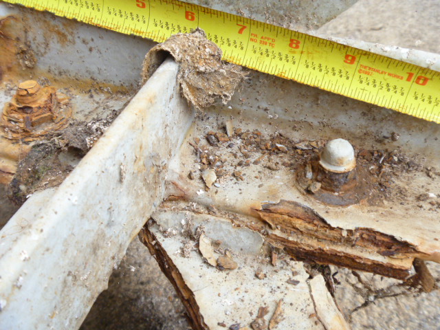
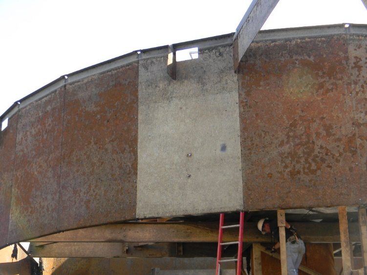
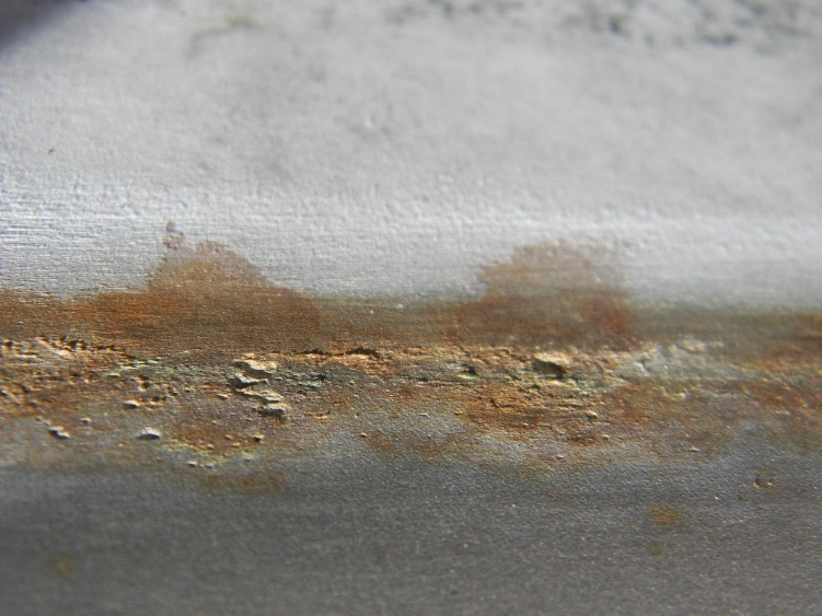
As discussed above, the immersed components of coated steel mechanisms are prone to oxygen-driven electrolytic corrosion. Coated carbon steel below the waterline is also susceptible to under-deposit pitting corrosion in both primary and secondary clarifiers. This corrosion involves differential oxygen concentration cells, and can be microbiological in nature, as well. Both mechanisms result in pitting corrosion, which occurs at breaches in the coating. This pitting typically has relatively high corrosion rates due to the large cathodic (coated steel) area relative to the very small anodic (coating failure or lack of coating) area as shown in Photo No. 1.
The organic resin-based coatings most widely used today on steel in clarifiers are based on epoxy and polyurethane chemistries. The epoxy-based coatings have mostly replaced coal-tar epoxy formulations, once the mainstay for clarifier steel corrosion protection. These newer epoxy coatings have good water resistance, excellent chemical resistance, and good film-build properties (12 to 30 mils per coat). The epoxy products are mainly used below the waterline, while epoxy first coats followed by an acrylic aliphatic polyurethane finish coat are chosen for areas above the waterline. The polyurethane provides UV light resistance and good color/gloss retention, where epoxies tend to chalk when exposed to sunlight. Some coating systems also utilize moisture-cured polyurethane primers followed by epoxy or polyurethane coats, as noted above.
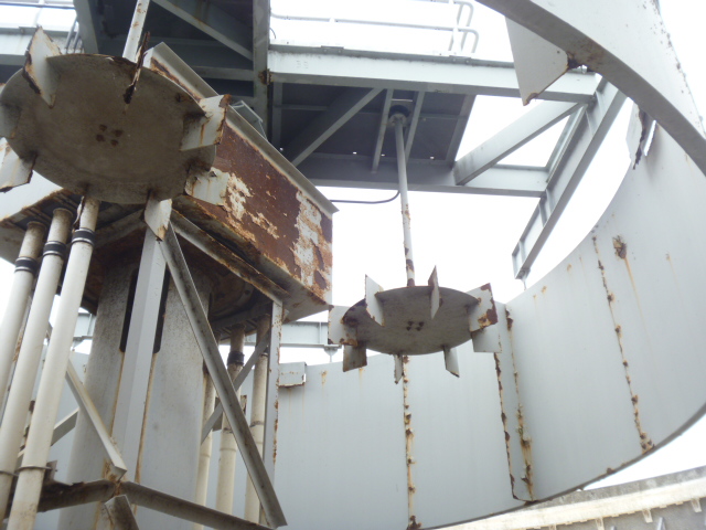
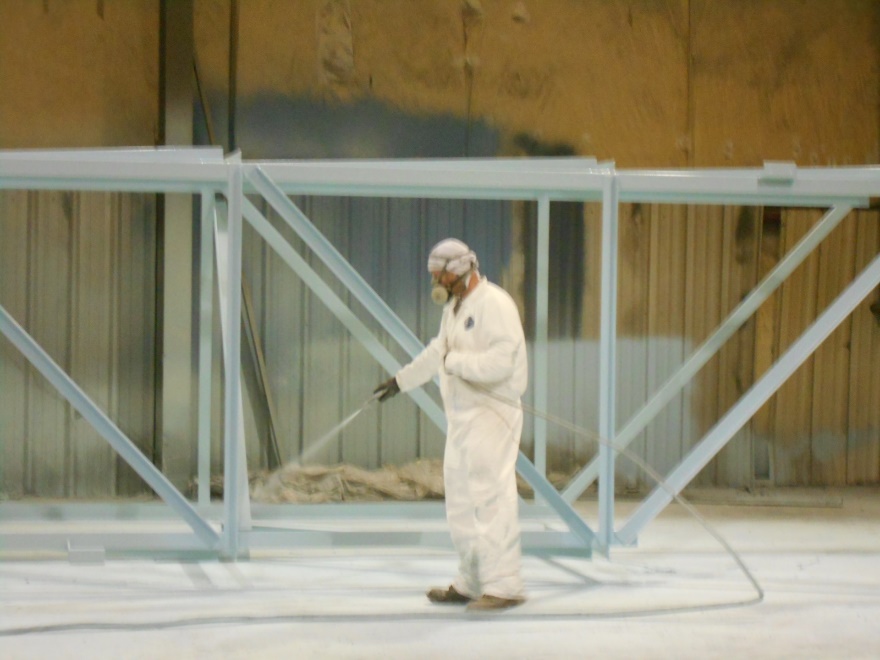
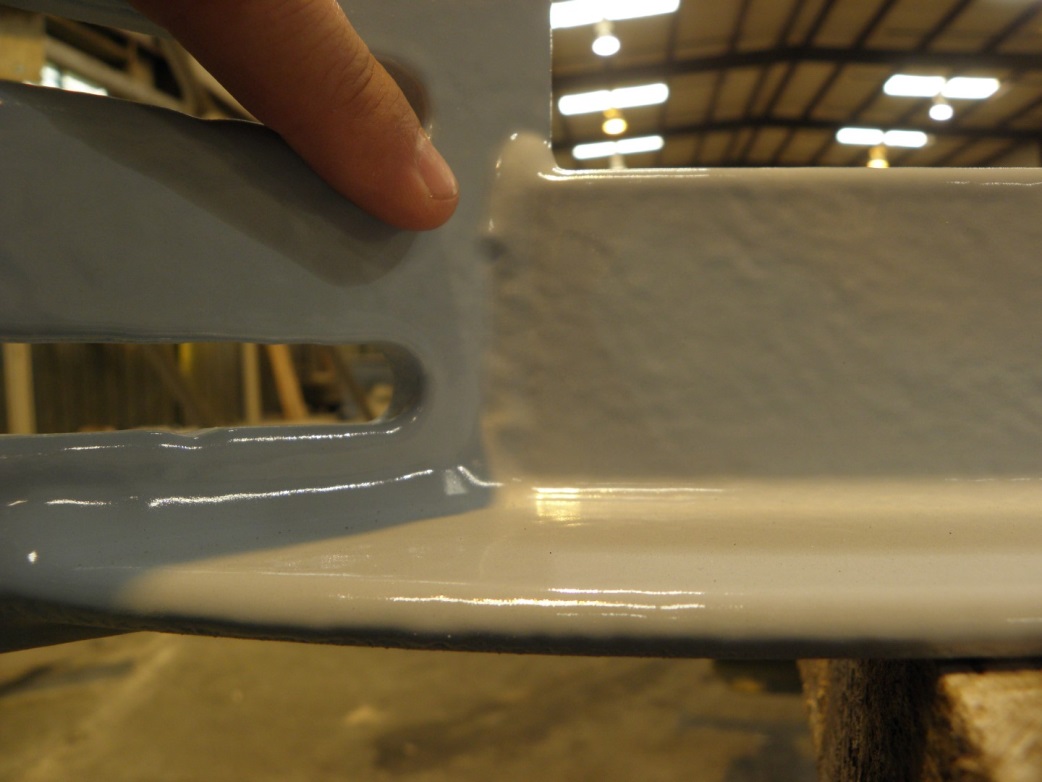
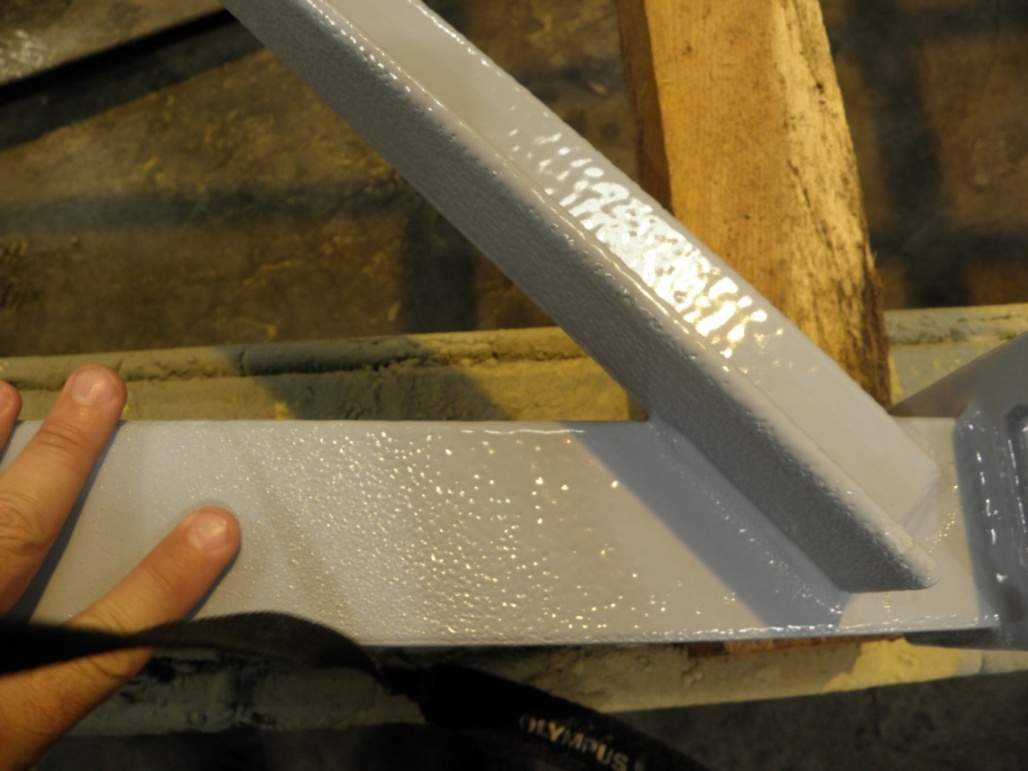
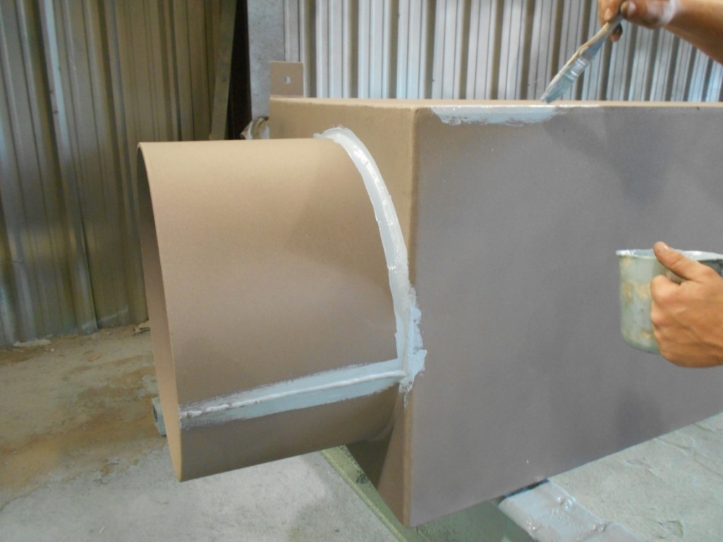
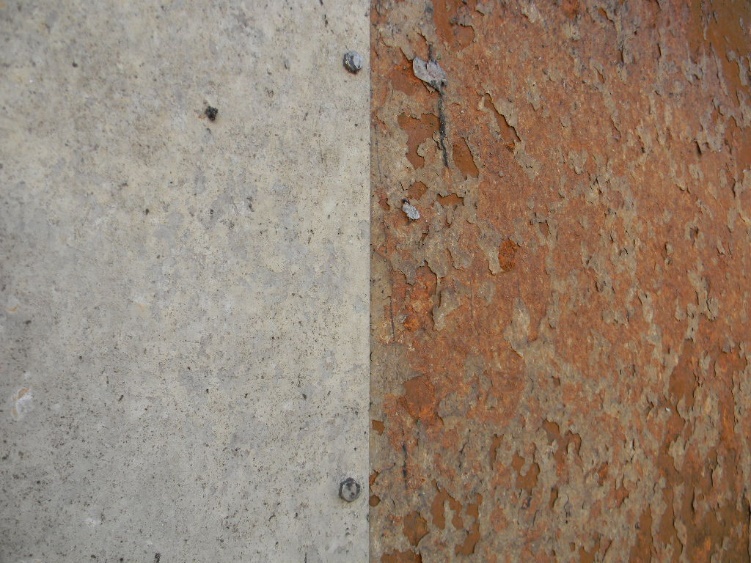
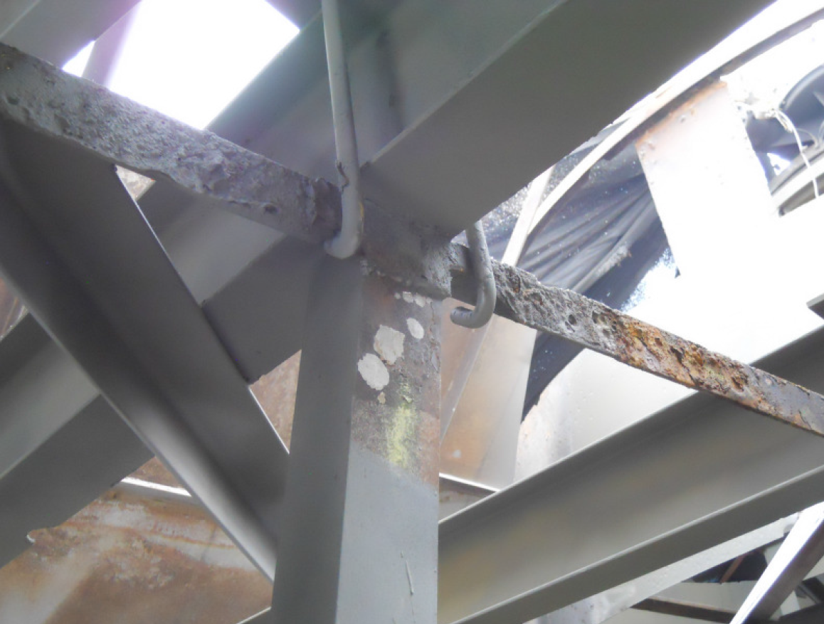
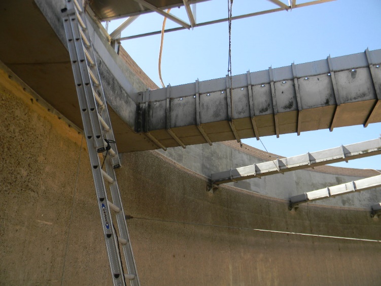
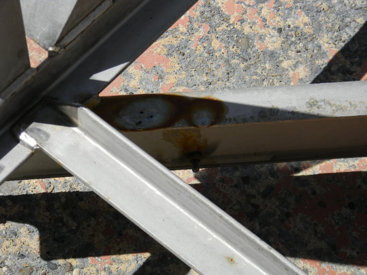
The main performance objective for coatings is to provide barrier protection and isolate the steel from the wastewater or headspace environment. To achieve this, the coating film quality must be ensured. This means minimizing pinholes or discontinuities in the film. This is difficult in clarifier construction because of the steel shapes used to fabricate rake arms and other clarifier mechanism components. Photo No. 2 demonstrates below waterline corrosion at areas of coating failure. Angles, channel, and other flanged shapes provide numerous edges, corners, nooks and crannies. So to achieve good film quality on these structures, great care must be taken in selecting and applying these coatings. Refer to Photo Nos. 3, 4, and 5 which demonstrate the attention to detail required for assuring good film quality. Those coatings that provide better edge retention and film build per coat are the best choices. And during application, “stripe coating” of the edges and corners is highly recommended to assure that good film quality and necessary film thickness are achieved. Stripe coating refers to the procedure of brush- or roller-applying each coat of the system over such edges prior to the spray application of each coat. Photo No. 6 shows stripe coating. Preventing pinholes, discontinuities and misses in the coating system is crucial for good barrier protection. This film quality focus and proper surface preparation are the hallmarks of good coating system performance in clarifiers.
Most properly selected and installed organic coating systems perform well in clarifiers for about 15 to 18 years before major coating repair work or recoating is required. Ongoing coating system inspection and more frequent coating system repairs have been shown to extend system performance, at a lower overall life-cycle cost for up to 25 years.
Protective coatings do not tend to fail from chemical degradation over time in clarifier service. Rather, coatings tend to age-harden, embrittle, or disbond due to undercutting corrosion that initiated at pinholes in the coating film.
Hot-Dip Galvanizing (HDG)
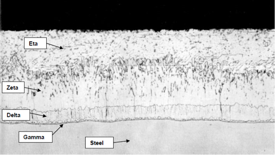
HDG represents the other most common corrosion barrier for carbon steel in general. HDG steel is a process whereby the steel is acid pickled (to prepare the surface) and dipped in molten zinc to form a zinc and iron alloy that has very good adhesion to the steel surface. When cooled, there is not a clear line of demarcation between the zinc and the steel, but rather a gradual transition of the zinc and iron alloy (see Figure 1). Starting at the bottom is the steel substrate. Next is a thin layer (“gamma”) that is typically 25% iron and 75% zinc, followed by the “delta” layer that is 90% zinc and 10% iron. Then comes the “zeta” layer that is about 94% zinc and 6% iron, with the final, “eta” layer at the top being 100% zinc. This is important to know because corrosion of the zinc and iron alloy can look like corrosion of the carbon steel base metal, especially at the lower layers (gamma and delta).
Zinc coatings are protective in two very different ways. First, they serve as a barrier coating to prevent the steel from contact with the electrolyte. Secondly, they act as a galvanic protector of the steel because they corrode preferentially to the steel when both metals are active in a common electrolyte and electrically coupled.
Zinc’s corrosion resistance is owed to the formation of an insoluble basic carbonate film in the case of atmospheric exposure. The contributing factors that affect the formation of that film are:
• duration and frequency of moisture contact (time of wetness);
• rate of surface drying;
• extent of exposure to corrodents.
In atmospheric exposures (where not corrosive), zinc reacts with air to form zinc oxide (ZnO) and later zinc hydroxide (Zn(OH)2). Ultimately, it reacts with atmospheric CO2 to form zinc carbonate (the most protective film). If moisture is present, increasing times of wetness correlate to increasing corrosion. If the atmosphere is not especially aggressive, the zinc forms a white powdery corrosion product called “white rust”. It is voluminous and does not permit the formation of a tightly adhered oxide film. This is not necessarily a major corrosion concern, but it does prevent the formation of a good barrier and keeps moisture present. This means more time of wetness and over time more corrosion.
For submerged conditions, the corrosion of zinc in water is mostly related to the impurities in the water; although pH, time of exposure, temperature, and motion (or agitation) are other contributing factors. As in atmospheric exposure, the corrosion resistance of zinc in waters largely depends on its initial ability to form a protective layer or film, such as calcium carbonate (CaCO3). In the case of distilled water, for example, there is no chance of formation of a protective scale. Hence, the access of O2 to the zinc surface is unimpeded and corrosion is quite severe. The scale forming capability of water depends for the most part on three factors as follows:
• hydrogen ion concentration (pH);
• total calcium content;
• total alkalinity.
If the pH of the water is below where the water can be in equilibrium with CaCO3, the water will dissolve the scale rather than deposit the scale. And while hardness and alkalinity are very important, and harder waters are better than softer waters, other factors must be considered. For instance, it is known empirically that waters high in free carbon dioxide (CO2) are aggressive toward zinc. Also, waters higher in dissolved O2 are more aggressive to zinc than those with lower dissolved O2. The corrosion of zinc in water follows this reaction:
Zn + 2H2O → Zn(OH)2 + H2
This reaction is complicated when lots of O2 is present. The O2 depolarizes and accelerates the corrosion reaction by combining with the evolved hydrogen. The end result is that the corrosion is largely driven by how much oxygen gets to the metal surface, which is the same driver of corrosion of uncoated steel in most waters. As reported in Uhlig’s Corrosion Handbook [2], the effect of oxygen on the corrosion of zinc in distilled water is demonstrated as follows:
Table 1. Effect of Oxygen on the Corrosion of Zinc in Distilled Water.
| Test Condition | Temp. | Corrosion Rate, Micrometers/Year |
| Boiled distilled water – specimens in sealed flasks | 72°F | 25.4
(1 mpy)* |
| Oxygen slowly bubbled through distilled water | 72°F | 218.4
(8.6 mpy)* |
*mpy = mils (0.001 inch) per year
Normal tap water at room temperature has a dissolved oxygen concentration of approximately 4 to 8 mg/l, which results in a theoretical corrosion rate for zinc of up to 3 to 4 mils per year. The zinc in the most aerated regions of clarifiers (typically near the inlet at the center well) would experience the highest corrosion rates where the dissolved oxygen concentration would likely be 8 or 10 mg/l.
As mentioned above, the pH of the water is critical to zinc corrosion and scale formation. It has generally been shown that zinc performs well at a pH of between 6 and 12, assuming no other corrosion contributors are present. But, that is not the case in wastewater clarifiers.
HDG typically produces an approximate upper coating thickness range of 4 to 6 mils. ASTM A123 requires about 3 to 4 mils of total zinc coating thickness for steel components[3]. However, only the outer 1.5 mils or so of that represents pure zinc. Below that the layers of the HDG come with increasing concentrations of iron and, once the iron-zinc layers of the HDG coating become exposed, the factors that influence carbon steel corrosion come into play as well.
An understanding of the combined influence of pH, calcium hardness, alkalinity, total dissolved solids concentration, and temperature is essential to discerning the corrosiveness of any water towards zinc. Those parameters can be utilized to examine the CaCO3 stability of the wastewater in accordance with the Langelier, Ryznar, and Practical Saturation Indices, to discern if the water would tend to form a protective CaCO3 scale on HDG steel. This is typically not the case in municipal wastewaters.
Another factor to consider for the corrosion of zinc includes chloride ion concentrations in the water. Where waters do not have the tendency to precipitate calcium carbonate scale, it has been reported that chloride ion concentrations of 50 mg/l or higher can be corrosive to zinc. [4]
Repair of HDG steel generally requires blasting and coating using a suitable organic coating system. The damaged HDG layer must be removed in its entirety. Coating over galvanizing is fraught with problems. Repair of small areas of failed galvanizing with field-applied galvanizing products can be done successfully with the right products and surface preparation; however, wholesale “galvanizing” of large structures in the field should be avoided.
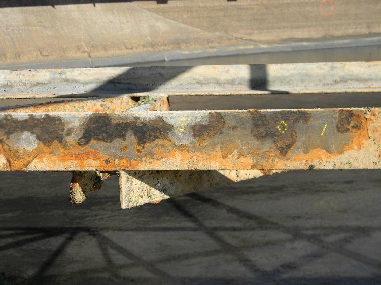
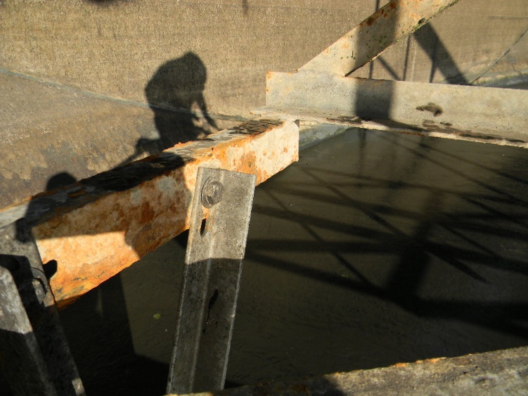
Photo Nos. 7, 8, 9, and 10 show the active corrosion of HDG coatings in a secondary clarifier rake mechanism and stilling well after only 1 year in service. Photo Nos. 9 and 10 show that where the HDG coating thickness was appreciably greater, the corrosion had not yet progressed into the lower delta or gamma layers.
Stainless Steel
In general, stainless steels avoid the general corrosion issues that plague bare or HDG steels in wastewater clarifiers. Stainless steels are iron-based alloys containing more than 11% chromium; this forms a thin, protective oxide film, which is the reason why this group of steels has their characteristic “stainless” nature or corrosion resistance. The ability of the oxide layer to heal itself (in most exposures) means that the steel is corrosion resistant no matter how much of the surface is removed. This is not the case when carbon steel is protected from corrosion by HDG or organic coatings.
The passive oxide film on stainless steels prevents corrosion except where certain exposure conditions cause it to break down or where it cannot be restored naturally. The most notable examples of these conditions include exposure to certain concentrations of chloride ions and microbiologically influenced corrosion. In addition, the presence of crevices or rough edges exacerbates corrosion under these conditions.[5]
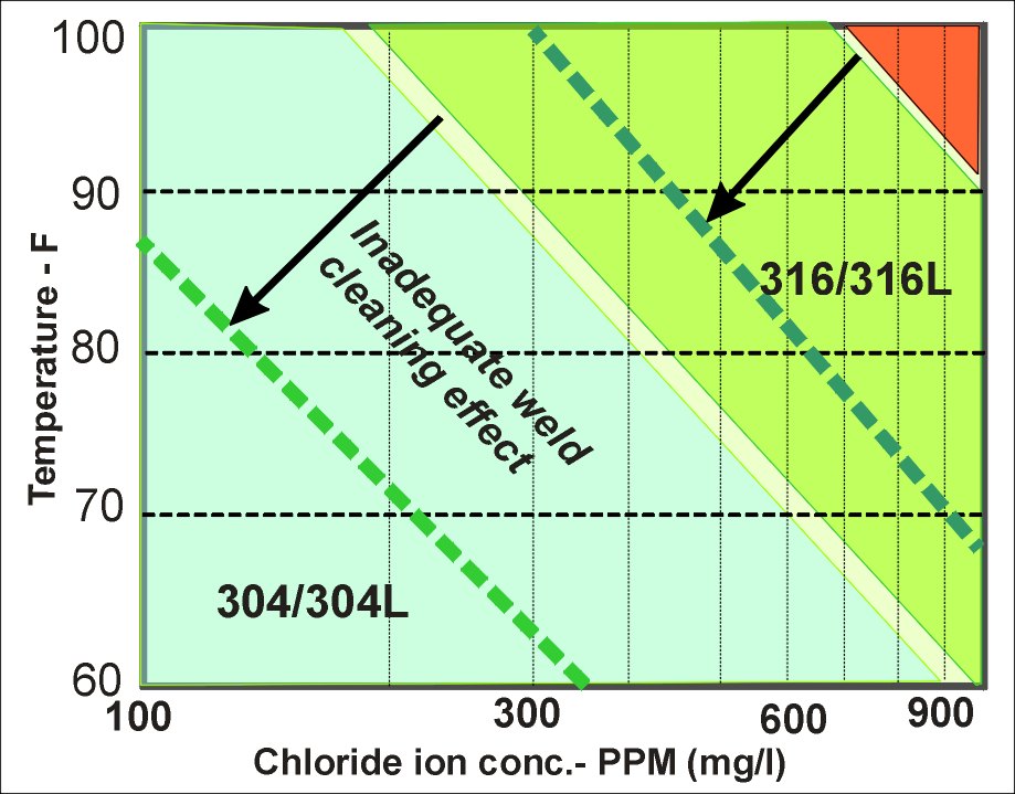
Chromium, nitrogen, and molybdenum contents in the alloy largely are what differentiate types of stainless steel with respect to pitting and crevice corrosion resistance. The major compositional difference between Type 304 and Type 316 stainless steels is the molybdenum content: 304 contains no molybdenum whereas 316 contains 2% to 3%. This makes the localized chloride-related corrosion (pitting, crevice) resistance of 316 superior to that of 304, as demonstrated in Figure 2.
While pH and temperature affect stainless steel corrosion, chloride concentration is the factor that most significantly promotes the breakdown of passivity and enhances the corrosion rate in clarifiers. Pitting and crevice corrosion occur when the passive oxide film is disrupted or broken down by chloride ions or other chemical species aggressive to the passivity. Certain chloride ion concentrations have been shown to initiate pitting and crevice corrosion in various stainless steel alloys under specific pH and temperature conditions. Extensive metallurgical and electrochemical testing has demonstrated that there are critical pitting temperatures, critical crevice corrosion temperatures, and corrosion threshold chloride concentrations for the different stainless steel alloys. These limits can be obtained from published data or laboratory corrosion testing. Also, corrosion engineers use a value called the pitting resistance equivalent number (PREN) to compare localized corrosion resistance for the various stainless steel alloys. This comparison is based on exposure to chloride-containing environments. Table 2 below presents the PREN for the stainless steel alloys most likely to be considered for clarifiers, assuming neutral pH and a temperature of 95°F. Approximate limiting concentrations for the chloride ion and relative cost also are listed.[6]
Table 2. Stai nless Steels: Chemistry, Chloride Pitting Resistance and Cost.
| Stainless Steel Grade | UNS1
Number |
Cr % (Typ.) | Mo % (Typ.) | PREN2 | Approx. Cl– Concentration Below Which Pitting does not Occur (ppm) 3 |
| 304L | S30403 | 18 | 0 | 18 | 300 |
| 316L | S31603 | 17 | 2.1 | 23 | 1,000 |
| 317LMN | S31726 | 18.5 | 4.1 | 32 | 5,000 |
| 2205 | S32205 | 22.5 | 3.3 | 34 | 5,000 |
| AL6XN | N08367 | 20.5 | 6.1 | 43 | Seawater level concentrations |
1 UNS = Unified Numbering System
2 PREN = Pitting Resistance Equivalent Number; %Cr + 3.3·%Mo + 16·%N, based on minimum composition
3 At 95°F
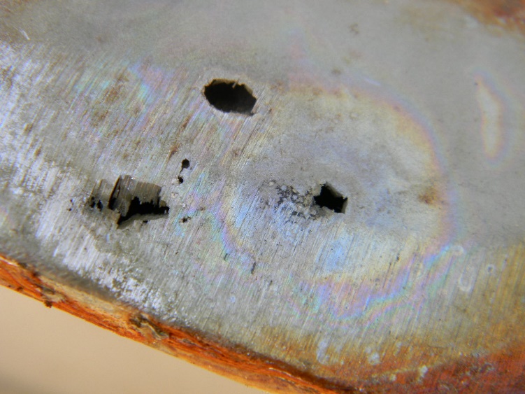
Pitting corrosion of stainless steels typically begins where deposits attach to the metal surface or where rough areas, such as welds, exist. Roughness and crevices are ideal environments for localized pitting and crevice corrosion. The passivity of the metal surface at rough areas is breached more readily, and crevices and rough surfaces enable chlorides to concentrate. This creates localized places where the chloride concentrations can exceed the metal’s pitting resistance. There are no better crevice conditions than threaded fasteners or flanged-gasketed connections. See Photo No. 11.
In addition, pitting corrosion tends to initiate at welds for metallurgical reasons. Weld metals and the heat-affected zones associated with those welds are less corrosion-resistant than the base metal. This has to do with metallurgical alterations created by weld heat, including segregation of the chromium at the metal surface.
Various process conditions can result in concentration effects with chlorides. These conditions can include wet/dry cyclic conditions, particularly common at or just above the water line in uncovered clarifiers in arid climates. At such locations, the chlorides concentrate on the stainless steel surfaces, especially where metal surfaces are hot from direct sunlight exposure (see Photo No. 12). Where this concentration occurs, chloride levels can be many times greater than in the bulk wastewater. This can lead to severe pitting corrosion. Again, this is particularly problematic at crevice locations such as flanged connections or on threaded fastener surfaces.
Microbial action also can promote the corrosion of stainless steel. This generally involves bacteria that metabolize (by reduction) sulfur compounds to produce sulfides in local environments on the metal surface. The latter condition produces oxidizing corrosion potentials. These bacterial corrosion processes drive microbiologically influenced corrosion (MIC). The sulfur-reducing environments produce highly acidic, underdeposit (beneath biofilm) conditions, which detrimentally affect passivity.
MIC occurs most often in primary clarifiers where stagnant or quiescent flow anaerobic conditions occur, at mostly ambient temperatures (within the sludge blanket). The corrosion rates can be extremely high. MIC also tends to develop at rough areas or at crevices, both of which are hospitable for microbial attachment and colonization. Typical examples include rough grind marks on rolled steel or stainless steel structural members, or the threads of fasteners (see Photo No. 13).
The 300-series stainless steels and 2205 duplex stainless steel are susceptible to MIC. Immunity to MIC typically requires an alloy that has a PREN of at least 40. This brings you to very expensive stainless steel alloys such as the so-called 6 moly stainless steels (AL6XN or 254SMO) or super duplex stainless steels like type 2507.
Stainless steels such as 304 and 316 tend not to suffer from localized corrosion when fluid velocity is at least 5 ft/s.
The corrosion resistance of welds always is lower than that of the same alloy’s base metal. Thus consideration should be give to upgrading the weld filler metal to enhance the corrosion resistance of stainless steel welds. For example, 316 electrodes would be used for 304L welds and 317 electrodes for 316L welds.
Maximizing the corrosion resistance of stainless steel welds also necessitates proper post-weld surface preparation and cleaning during fabrication (shop) and erection (field). This starts with careful mechanical removal of all weld slag, which includes grinding to remove weld spatter and rough weld areas. Additionally, all heat tint (bluish hue on the metal surfaces) should be removed by grinding and/or grit/bead blasting, followed by acid pickling to remove any remaining free iron. If not properly cleaned, these areas will be susceptible to localized corrosion due to the reduced resistance of this chromium-depleted metal surface area.
Galvanic Effects
Electrically connected, dissimilar metals immersed in either primary or secondary clarifiers create ideal conditions for galvanic corrosion. Galvanized steel generally does poorly in these environments, and carbon steel readily corrodes preferentially to stainless steel.
As with all galvanic corrosion, the rate is mainly governed by the electrochemical potential difference between the two electrically continuous metals, their proximity to one another, and the anode-to-cathode area ratio (a small anode with a large cathode is the worst combination).
The most common galvanic corrosion observed in wastewater clarifiers is localized pitting of carbon steel (at coating breaches) near stainless steel components like suction tubes. Because suction tubes cannot be recoated on the interior after initial construction, the use of stainless steel has become the standard material of choice. Electrical isolation of the stainless steel suction tube from the coated carbon steel is necessary to prevent galvanic corrosion.
Sometimes, failed carbon steel structural members on rake arms are replaced with stainless steel, which will affect corrosion of connected carbon steel components.
The corrosion rate of the anodic material will generally be highest at the dissimilar metal connection, and decrease with increasing distance away from the connection. Electrical isolation between dissimilar metals can be achieved at bolted connections by installing isolation bolt kits. However, the insulating spacers can degrade over time and re-introduce electrical continuity. If only welded connections exist, stainless steel in contact with coated carbon steel can be coated at the connection, plus some distance beyond the connection to achieve effective electrical isolation.
When selecting materials of construction for wastewater treatment plant clarifier mechanisms, one must understand the operating environment, the candidate materials and their properties, and the damage mechanisms caused by interactions between those materials and the environment. Also important are fabrication and erection practices and their effects on corrosion resistance of the materials.
Carbon steel protected by a suitable organic coating system remains a viable option for both new and rehabilitation construction. A tight and enforceable specification for the work, along with good quality control during fabrication and erection are crucial for long service life. Still, the nature of such coatings makes periodic inspection (with the associated costs for dewatering, cleaning, access, etc.) necessary, and the best coatings will likely last less than 20 years if not well applied and well maintained.
HDG steel is an alternative to coated steel, but will have a high susceptibility for failure in most wastewater clarifier environments. The fact that the coating is metallic brings into play more issues than for organic coatings, such as scale formation and galvanic effects. As with organic coatings, regular inspection is required. Additionally, when the galvanizing finally goes away, it cannot be replaced with new galvanizing. Using HDG for clarifier mechanism corrosion protection can be done if all the conditions are right, but it is very risky.
Stainless steels are a step above coated steel in most cases. The higher initial material costs are typically offset within the first 10 years of clarifier operation by lower inspection and repair costs. Stainless steels, though, can have issues—expensive ones—if not selected properly for the operating conditions, and/or if not fabricated so as to eliminate those issues. Again, a tight and enforceable material and fabrication specification, along with good quality control during fabrication and erection, are crucial.
1. Corrosion and Materials Fundamentals for Engineers in Water and Wastewater Treatment Plants, Corrosion Probe, Inc., 2007.
2. Uhlig’s Corrosion Handbook, R. W. Revie (Ed.), Wiley, 2011.
3. ASTM A 123/A 123M – 02, Standard Specification for Zinc (Hot-Dip Galvanized) Coatings on Iron and Steel Products, ASTM International, 2002.
4. Philip G. Rahrig, “Galvanized Steel in Water and Wastewater Infrastructure”, Materials Performance, NACE International, July 2003.
5. R.A. Nixon, “Deterioration of Wastewater Treatment and Collection System Assets: Knowing Where and How to Look”, SSPC: The Society for Protective Coatings, PACE, 2006.
6. R.A. Nixon, “Stainless Steel and Corrosion Behavior – Understanding the Use of Stainless Steels in Wastewater Applications”, WE&T Magazine, Water Environment Federation, September 2014.