
Protective coatings are used in anaerobic digesters to achieve both corrosion protection and gas tightness. With respect to the need for corrosion protection, anaerobic digesters, under typical operating conditions, do not create exposures which are corrosive to either carbon steel or concrete substrates. This paper will explain the basics of how anaerobic digesters work chemically to stabilize biosolids and demonstrate the atypical operating conditions under which corrosion becomes problematic. This involves unintended or unexpected process upsets in existing digesters as well as anticipated, short-lived start-up conditions in new digesters. When these inadvertent or predictable corrosive exposures occur, selection of the right protective coating system is of paramount importance. This paper will describe its author’s experience with corrosion and coatings in various types of anaerobic digesters including concrete vessels with steel floating covers, concrete and steel vessels with fixed covers, and egg shaped digesters. Through the examination of project learnings from specific digester types, commonplace corrosion and coatings performance problems will be identified along with recommended criterion for selecting appropriate protective coating systems. Furthermore, the selection of protective coatings to ensure digester gas tightness will be discussed.
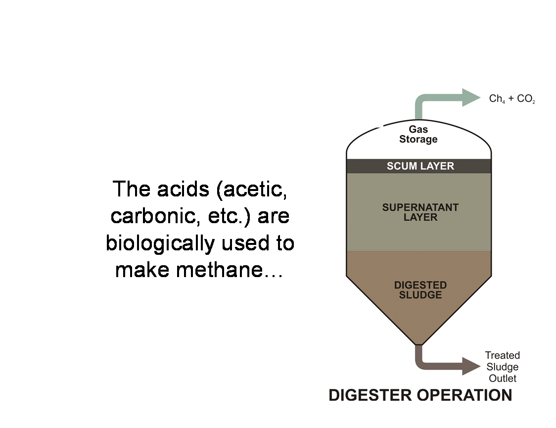
Anaerobic digesters are vessels in which biosolids (sludges) generated in the primary wastewater treatment process are biologically converted to a stable condition for agricultural use or landfill disposal. This stabilization process (reduction of pathogens and odors) involves many complex biochemical reactions. The result is the production of stable biosolids at a relatively moderate cost with the bonus of producing methane gas that can be used for energy production. Figure 1 shows a schematic of a typical cylindrical anaerobic digester.
This author has performed condition assessment inspections of many anaerobic digesters in municipal wastewater treatment plants over the past 35 years. These condition assessments of various digester design types have included both mesophilic and thermophilic digesters in which normal operating temperatures are 95oF (35oC) and 131oF (55oC) respectively. Process-side corrosion damage has only been encountered in these inspections when one of three scenarios has occurred:
1. The digester had been shut down due to power failure or mechanical problems resulting in the loss of anaerobic conditions wherein volatile acid concentrations rose and free oxygen was present over an extended time period.
2. New digesters were started-up prior to the establishment of the required biotransformation of the organic compounds needed to chemically stabilize the sludge. Another way to say this would be: The right bugs weren’t sufficiently present for sludge stabilization and corrosive conditions prevailed.
3. The chemical composition of the influent sludge to the digester was unexpectedly high in certain toxic elements or compounds which prevented normal biogenesis from occurring. These compounds can include light metal cations like calcium, unusually high dissolved hydrogen sulfide, and heavy metals such as zinc or chromium, and other chemical constituents.
In all three cases described above, the sludge pH became very low and/or the sludge contained unexpectedly high toxic chemical concentrations which blocked the biochemical reactions necessary for normal sludge stabilization. When the sludge in anaerobic digesters is too acidic (pH is below 6.0), not only does sludge stabilization fail, but corrosive conditions develop. If free oxygen is present, the sludge goes “sour” or acidic and corrosion rates for unprotected carbon steel and Portland cement can be high. Even when digesters are cold started (not related to temperature, but referring to new start-up prior to biogenesis development in the sludge) and remain under anaerobic conditions, volatile acid concentrations can become sufficiently high to promote aggressive steel and concrete corrosion.
Under normal operation, acid formation occurs naturally and continuously in digesters and lowers the pH of the biosolids. However, the on-going bio-formation of methane creates alkalinity, mainly in the forms of ammonia and carbon dioxide. When combined with the hydrogen ions present, these substances buffer the pH. When toxic materials kill or make bacteria unhealthy, the normal acid production continues unheeded and methane and alkalinity formation are inhibited. This leads to a build-up of volatile acids. This results in the need for corrosion protection which is best accomplished with properly selected and applied protective coatings.
Another major reason for using protective coatings in anaerobic digesters is to prevent the leakage of gas (mainly methane) from the vessels. This is important for personnel safety reasons and to loss of revenue. Methane is burned and used for energy both for heat transfer (as in biosolids drying) and for electric power generation. Gas tightness of the digester is generally achieved through the application of protective coatings which seal cracks or joints in concrete digester covers. Historically, flexible polyurethane coatings have been used for this purpose, but rigid cured epoxy linings installed with integral crack bridging or sealing detail treatments can also perform successfully in these applications. The use of protective coatings for corrosion protection is commonplace in the United States for concrete digesters with fixed concrete and steel covers. However, this practice is not mandated for gas tightness by either state or federal regulations. In Canada, on the other hand, the use of coatings sufficiently flexible to ensure gas tightness for concrete covered digesters is required by the Canadian Federal Government. The relevant Canadian Federal Regulation is CSA-B105-M93. This regulation also sets forth specific gas tightness testing methods and pass/fail criteria. It must be adopted by the individual provinces, but has not to date been accepted by all ten of them.
The overarching point of this paper is protective coatings are necessary for both corrosion protection (when needed) and gas tightness (where required) in anaerobic digesters. Accordingly, the proper selection, prior surface preparation for, and application of protective coatings inside anaerobic digesters are essential.
Under normal operating conditions, anaerobic digesters contain sludge which contains or emits certain concentrations of methane (CH4), carbon dioxide (CO2), and hydrogen sulfide (H2S) in dissolved and gaseous forms. Alone, these compounds can all be corrosive, but are not when present in a digester atmosphere in which no free oxygen is present and where the pH of the sludge is near-neutral. Above we have described digester operating conditions under which corrosion can occur aggressively where appropriate protective coating use is crucial. Therefore, it only seems appropriate here to briefly explain chemical process basics for anaerobic digestion.
The anaerobic digestion process consists of three phases or stages of complex biochemical reactions. The initial stage is hydrolysis of the organics in the sludge including proteins, cellulose, and other materials which become soluble. This hydrolysis stage takes particulate matter and solubilizes it such that it can be further hydrolized to form single monomers which can be used by bacteria that perform fermentation.
In the second phase of reactions, the products from the hydrolysis phase are converted into complex compounds including long-chain fatty acids. As the second stage bio-chemical reactions proceed, these long-chain fatty substances are further broken down to form short-chain organic acids. This second stage is the fermentation phase, also called acidogenesis. The fermentation of amino acids, sugars, and fatty acids produces organic acids including those derived from acetate, hydrogen, and carbon dioxide.
The third stage of digestion involves the action of a particular type of bacteria called methanogens. One group of methanogens split acetate into methane and carbon dioxide while another group uses hydrogen as an electron donor and CO2 as an electron receptor to produce methane. The gases which come out of solution in the top (gas space) of anaerobic digesters are mainly methane and CO2. This stage is called methanogenesis. The volatile acids which are formed by the second stage (acidogenesis) include acetic acid and carbonic acid. These acids reduce the sludge pH. However, this pH reduction is typically buffered during methanogenesis as described above. This keeps the sludge pH at or close to neutral in the digester. But as indicated earlier in this paper, certain compounds including toxins found in the incoming sludge can prevent proper biogenesis in the digester causing low pH, corrosive conditions to evolve. When upset conditions occur, the sludge pH in digesters can go down to 3.0 or less. And when free oxygen is allowed to be present, sulfur acids and carbonic acid can be formed which are very aggressive to unprotected carbon steel and concrete substrates.
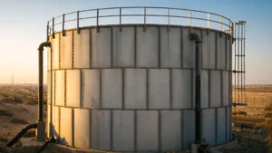
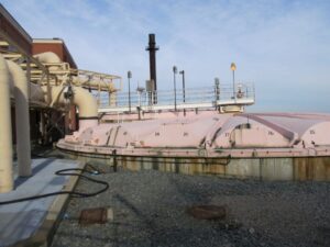
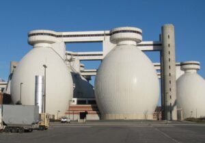
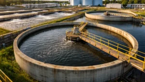
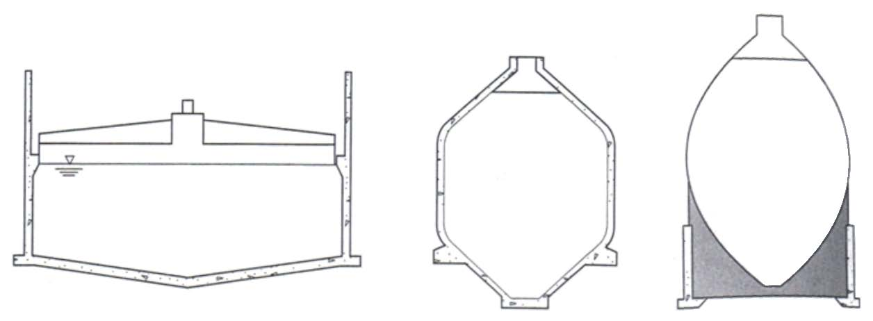
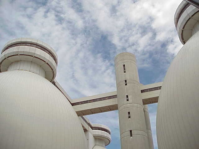
Worldwide, the most common types of anaerobic digester tanks are either cylindrical, conventional German design, or egg-shaped. Refer to Figure 2. The most common shaped digesters used in North America in the past were shallow, vertical cylinder shaped digesters with either floating or fixed covers or roofs. See Photo No. 1. The egg shaped digester (the second generation of the German design) are utilized extensively in Europe and are growing in popularity in North America. See Photo No. 2. Each design type has its pros and cons. Cylindrical digesters allow large gas volume storage, but are not well suited for good sludge mixing. Cylindrical digesters have large surface areas for top of liquid scum and foam formation and poor mixing creates grit accumulation. Egg shaped digesters reduce scum formation due to their shape and provide for better mixing and hence minimize grit build-up. In addition, egg shaped digesters provide very little gas storage volume and cost more to construct than cylindrical digester tanks.
Cylindrical digester with floating German type digester. Egg shaped digester. cover.
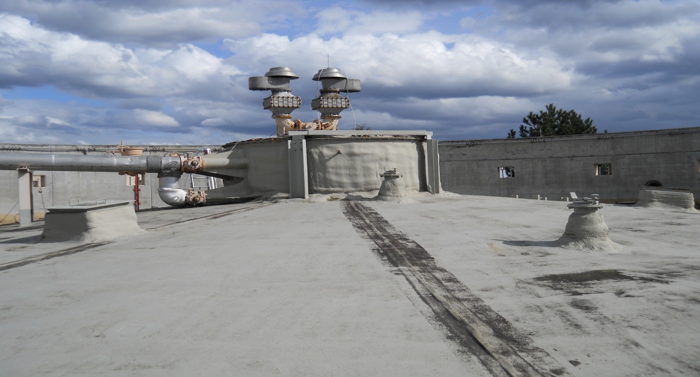
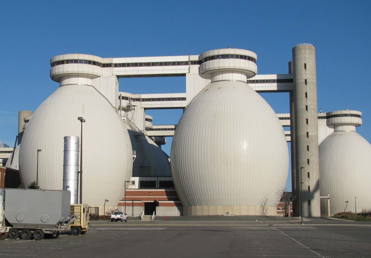
Up until the 1990’s, cylindrical digesters were still being constructed with floating carbon steel covers to allow for varied gas storage volume depending on digester sludge loading. Floating covers are rarely utilized in new design today, but many such digesters remain in service. A common retrofit practice today is to replace or modify steel floating covers with fixed steel covers. Many new cylindrical digesters are constructed with reinforced concrete fixed covers. Cylindrical digester tanks typically consist of reinforced concrete walls whereas egg shaped digesters are built entirely from welded steel construction with reinforced concrete foundations.
Egg shaped digester tanks and the steel covers for cylindrical digester tanks are externally coated for corrosion protection and insulated to maintain internal operating temperatures. This can include aluminum jacketing over the insulation or protective polyurethane coatings over spray applied polyurethane foam insulation for weather protection. This paper does not address external corrosion protection of carbon steel digester tanks or tank components except to point out here that corrosion under-insulation (CUI) has been reported particularly with digesters located in coastal environments where chlorides have concentrated beneath insulation systems and external coatings were improperly applied.
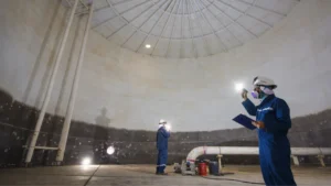
Floating cover digesters generally consist of cylindrical tanks with a floating carbon steel pontoon type roof structure. This cover consists of a sloped steel roof, a flat floor and an internal structural system of trusses, and steel walls including a skirt as shown in Figure 3. This cover rises and falls with changes in the digester’s gas volume. The most common corrosion and protective coatings issues experienced with floating steel digester covers are described below.
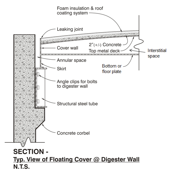
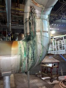
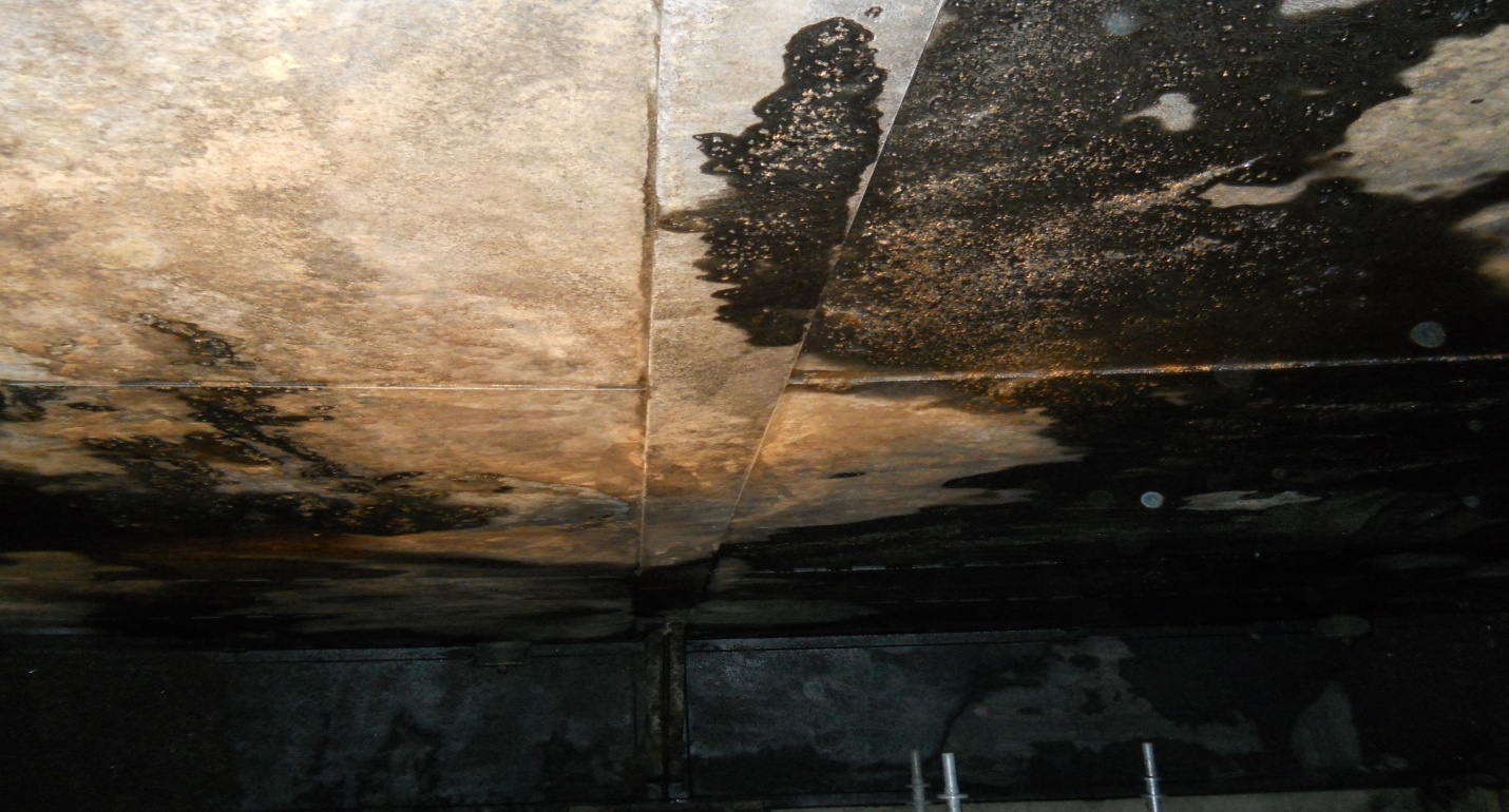
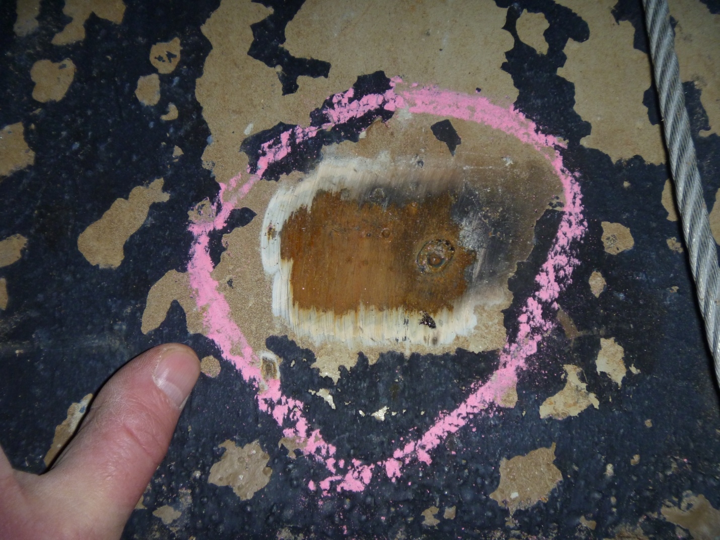
When digesters come out of service unexpectedly or experience upset conditions as described earlier in this paper, both gas phase and liquid phase corrosion of carbon steel can occur. Photo Nos. 3, 4, 5, and 6 demonstrate pitting corrosion of coated carbon steel in a floating cover when upset conditions occurred and the digester was exposed to acidic conditions for several months. The corrosion damage was greatest where the original coal tar epoxy coating had previously failed or disbonded. Further damage developed as undercutting of the coating progressed from exposure to the low pH conditions. High CH4 (methane), CO2, and H2S gas exposure in the presence of free oxygen allowed this digester to go “sour” and create corrosive conditions. The upset conditions were caused by mechanical jamming of the floating cover guide rollers which allowed the cover to be wedged off center causing loss of its air (or gas) tight seal. Note the blistering which developed in the existing coating on the bottom of the floating cover as shown in Photo No. 5. Blistering was also present on the outside of the cover’s skirt.
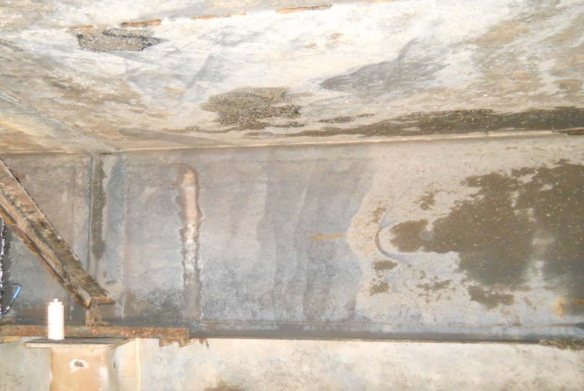
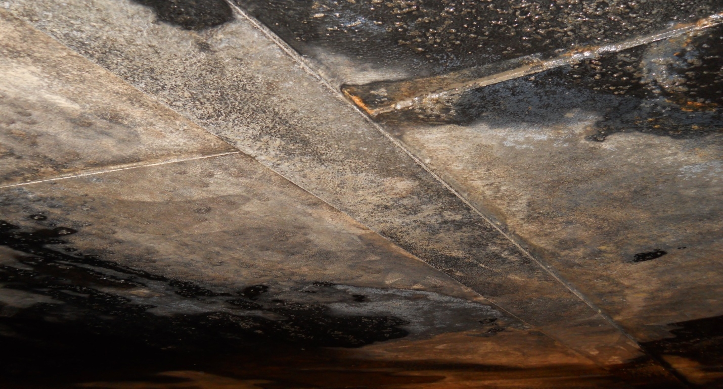
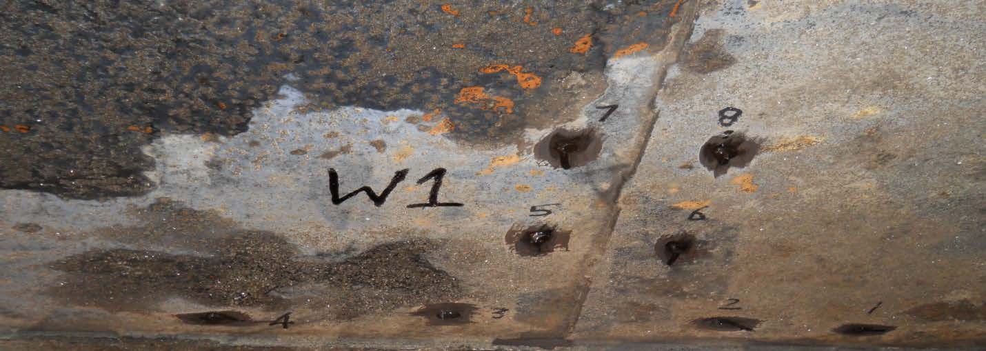
The existing coal tar epoxy coating applied on the process side surfaces of the floating cover (the cover bottom and skirt) performed fine for over 25 years under normal digester operating conditions. However, when the tank experienced upset conditions, the combination of acidic gases and volatile acids in the sludge were too aggressive for the aged coating system. Carbon steel corrosion and permeation driven blistering of the existing coating resulted.
This digester cover was subsequently repaired and completely recoated. The new coating system consisted of a blended amine cured bisphenol F epoxy system applied at 30-35 mils DFT. The carbon steel was first abrasive blast cleaned to a white metal degree of cleanliness in accordance with SSPC-SP5. This coating system was selected for the following reasons:
• Excellent resistance to volatile acids down to a pH of 1.0 or less.
• Very low permeation resistance to gases and volatile liquid acids with small molecules including methane, water, carbon dioxide, hydrogen, and hydrogen sulfide.
• Good film build for edges of structural steel shapes and edges of steel plates.
• Good amine blush resistance. (Humid conditions are common inside digester tanks.)
• Good moisture tolerance during cure and cure capability down to 45oF (7oC).
• Self-priming capability and high film build (up to 20 mils) per coat.
• Good substrate wetting capability to ensure tenacious adhesion to properly profiled and cleaned steel substrates.
• 100% solids coatings are essential as application invariably occurs in confined spaces.
The new coating system has been in service for over 6 years. No process upset conditions have occurred since the digester went back into service. However, the replacement coating system was selected to resist such process upset conditions should they recur in the future.
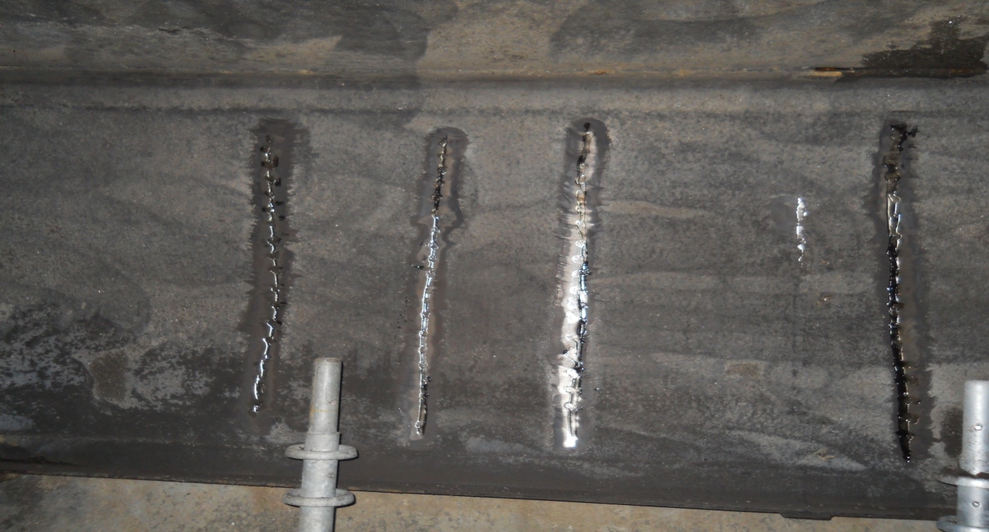
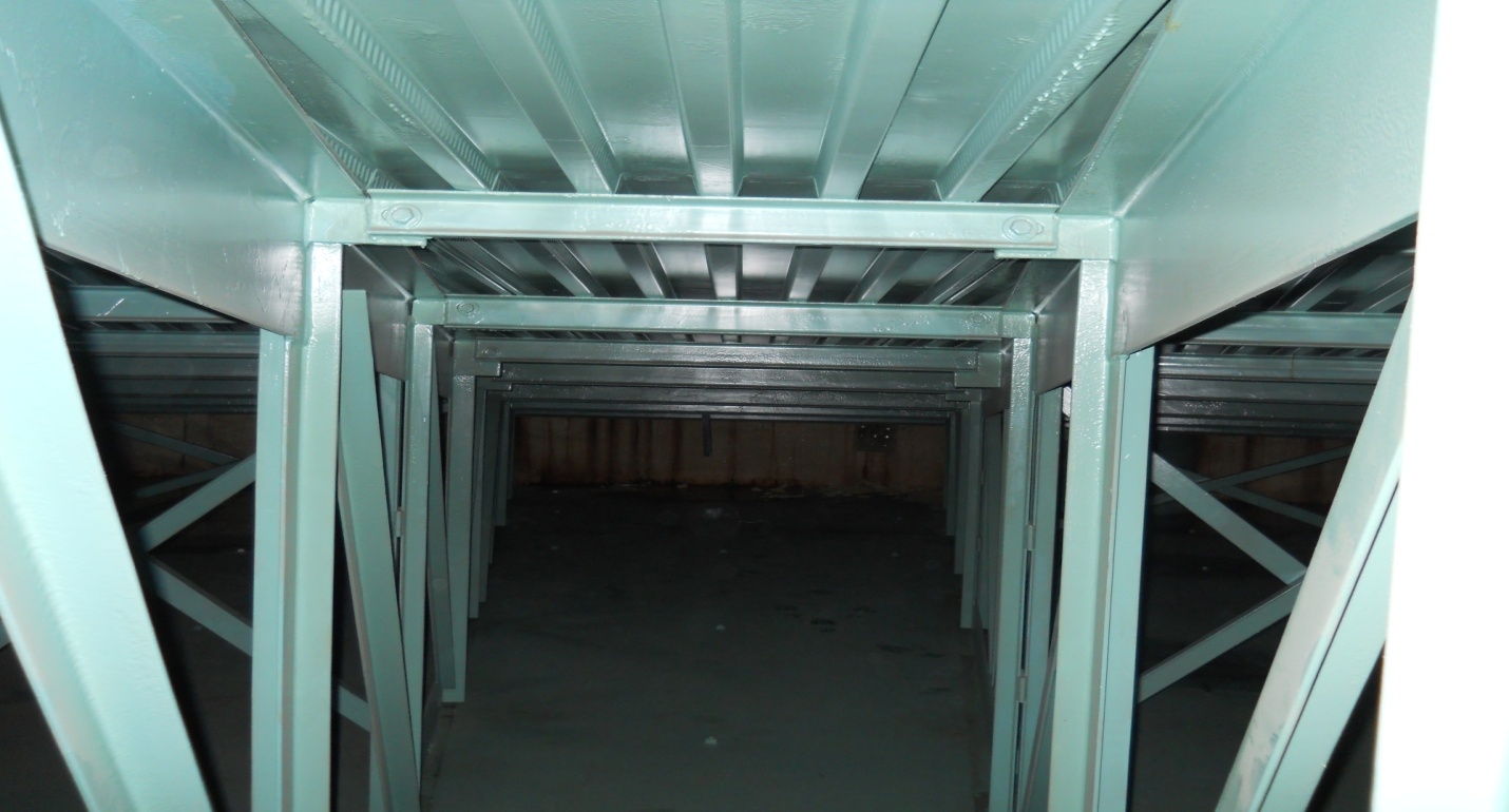
The interstitial space in floating steel digester covers exhibit corrosion issues despite normal biochemical operation in the digester. These spaces tend to routinely experience warm, condensing, and well aerated conditions, all conducive to carbon steel corrosion. Therefore, good protective coating performance (especially good adhesion and film quality) are essential under normal digester operating conditions. Condensed water often collects on the top of the cover floor creating corrosive pooling conditions. Also because these covers are constructed with literally thousands of lineal feet of welds (including skip welds), pinhole free coating films and leak tight conditions are rarely achieved. Photo No. 7 shows floating cover roof leakage while Photo No. 8 demonstrates typical coating repairs to the floors found in the interstitial spaces of floating covers.
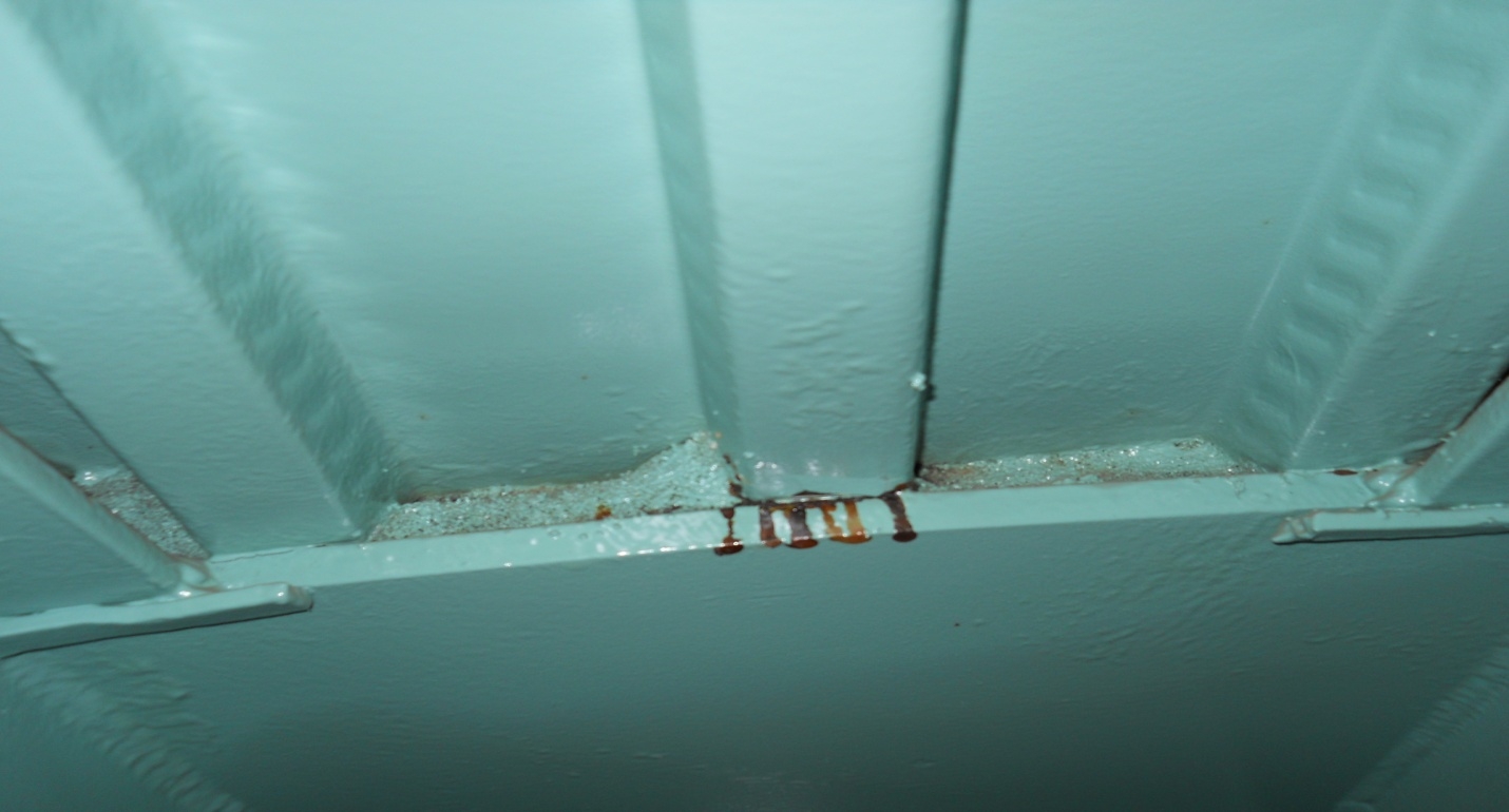
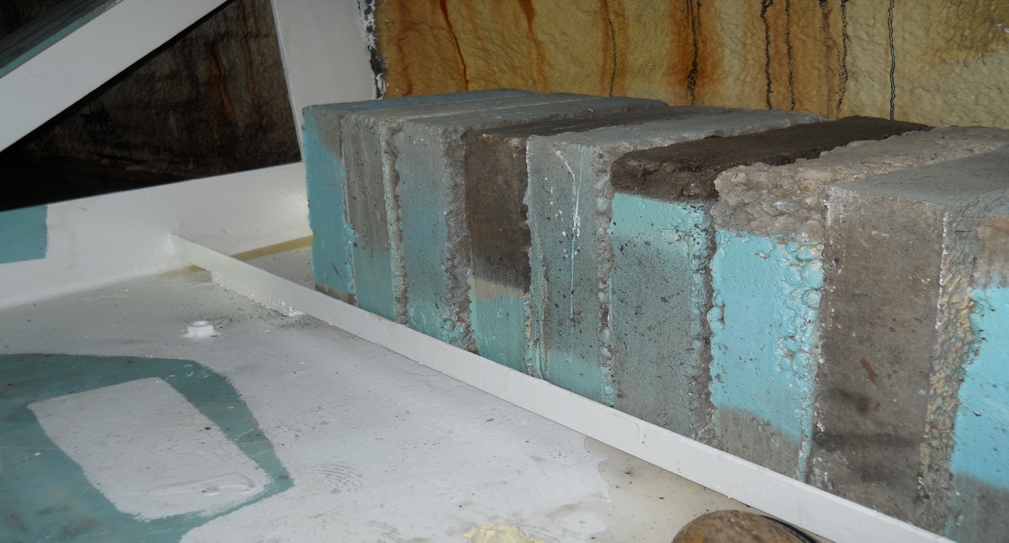
Another frequent contributor to floating cover corrosion and coating failure is the leakage of digester gases and sludge into the interstitial space. Photo Nos. 9 and 10 show biosolids leakage between the cover walls and roof panels into a floating cover. Because liquid sludge and foam is actually used to create the gas tight seal for floating covers, penetrations in the steel cover provide leak paths into the interstitial space. The result is corrosive conditions. Photo No. 11 which shows a floating cover digester in service, demonstrates how this leakage can develop. Leaks in welds found in the bottom of floating digester covers can also create very corrosive conditions for unprotected carbon steel.
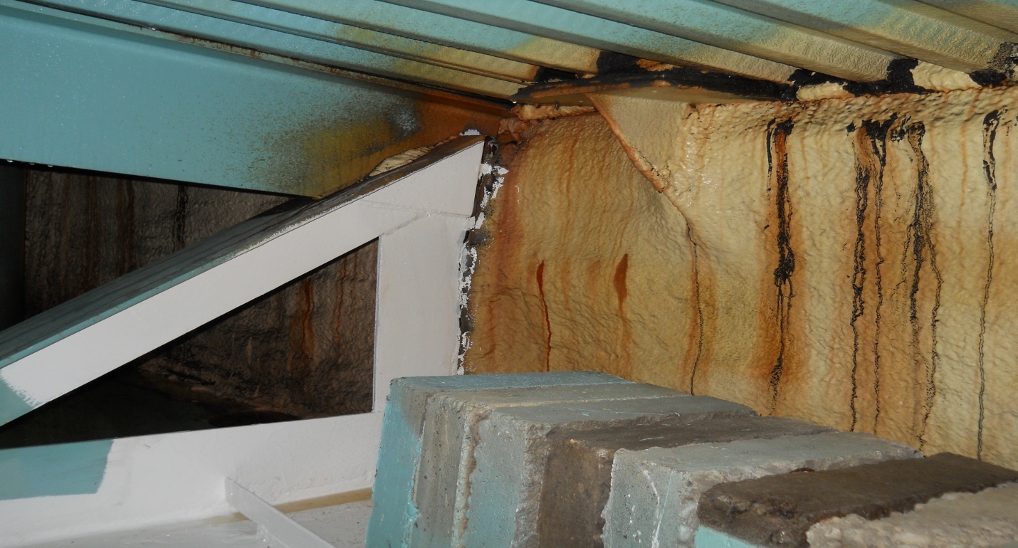
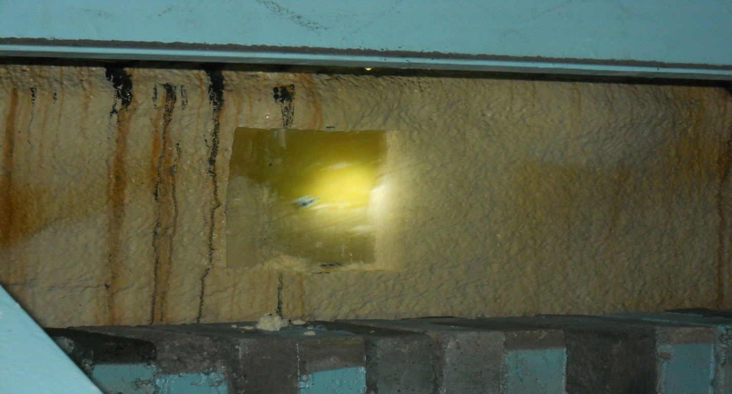
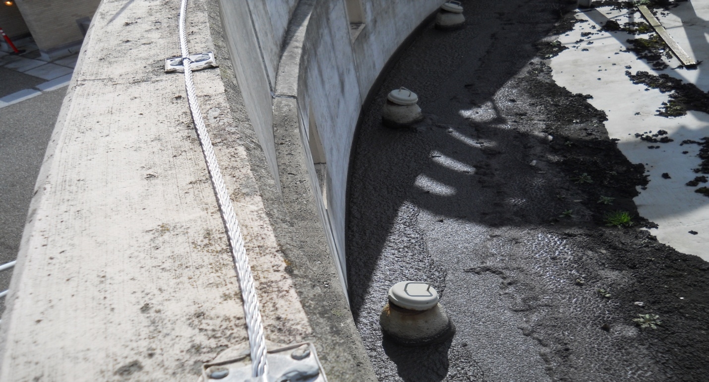
When selecting protective coating systems for corrosion protection of the interstitial spaces in floating digester covers, most of the criteria set forth above for the process side of floating steel covers are pertinent. The main exception includes film build properties. The total film thickness for the interstitial space surfaces need only be up to 20 mils DFT. Low pH (down to 1.0) and bacterial breakdown resistance are also important selection criteria. So, polyamide and amidoamine cured epoxies are poor choices here due to their susceptibility to bacterial metabolism. Amine cured epoxy formulations which are resistant to “blush” problems including some phenalkamine and specialty blended amine systems can perform well here as can some micaseous iron oxide (miox) filled moisture-cured polyurethane coatings. These applications are no place for plural component applied products due to tight interstitial space restrictions. Hence, typical airless spray application is a better approach. Due to limited access and the confined space nature of these cover interiors, all coatings must be 100% solids by volume to ensure personal safety from an air quality standpoint. Photo No. 12 shows one view of a newly coated interstitial space in a 40 year old digester. A two-coat cycloaliphatic amine cured coating system was used for this project 16 years ago. Subsequent inspection revealed outstanding performance despite sludge leakage into the cover. However, amine blush problems were experienced and overcome during the application.
Fixed steel covers on cylindrical digester tanks should not experience aggressive corrosion or premature coating failure if the vessel operates under anaerobic and normal biochemical conditions as discussed earlier in this document. However, like the process side of floating steel covers, fixed steel covers can be exposed to significant corrosion rates under process upset conditions. Refer to Photo No. 13 which shows coating failure and carbon steel corrosion on a fixed steel cover in a digester that was started up cold (meaning new). For this reason, the same protective coating selection criteria recommended above for the process side of floating steel covers should be followed for fixed steel covers.
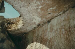
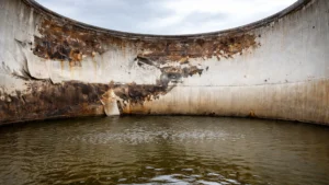
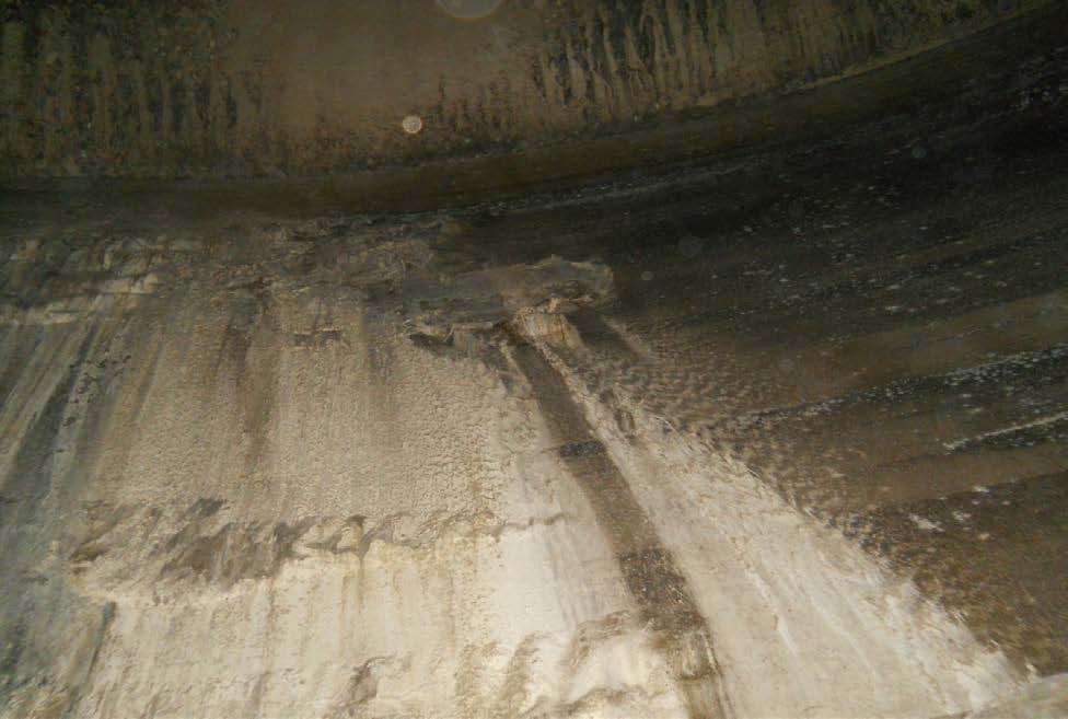
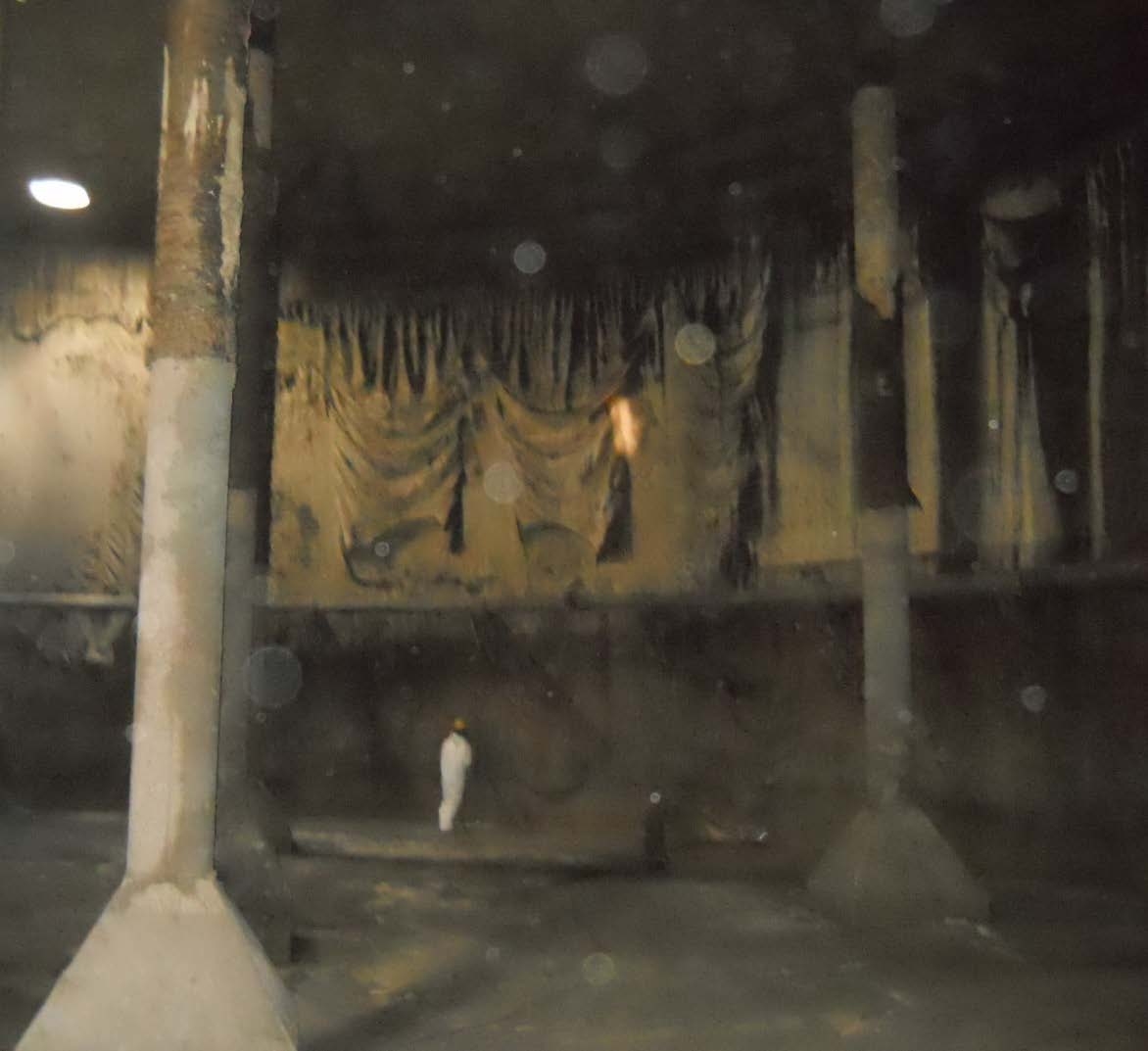
Concrete fixed roof digesters remain a common design type in North America. Typically, these digesters are internally coated only to accomplish gas tightness. Again, under normal operating conditions, the pH of the sludge in the digester is near neutral and concrete does not suffer acidic attack or other forms of degradation. Hence coatings are commonly used only in the gas storage space in the digester plus some distance (approximately 2 to 3 meters or 6 to 9 feet) below the normal liquid operating level in the tank. The remainder of the concrete walls and the floor surfaces of the digester are not coated. This is common practice and problems only occur when upset conditions or the “cold start” scenarios described earlier are experienced. Photo No. 14 shows cement paste losses in a concrete digester that was started-up in a new wastewater treatment plant prior to the establishment of normal digester biogenesis. The digester operated at a pH of 3.0 to 5.0 for a number of months. This caused acidic attack of the concrete’s otherwise highly alkaline Portland cement paste below the internally coated surfaces of the tank. The headspace or gas storage space in the digester was unaffected as it was well protected by the original polyurethane lining. Later, all of the digester’s concrete walls were abrasive blast cleaned, high pressure water cleaned, resurfaced with a cementitious mortar, reblast cleaned, and properly lined with a flexible aromatic polyurethane lining. That lining was installed 7 years ago and has since performed extremely well based on recent reinspection reports.
A concrete digester tank was relined in 2002 with a fully adhered, flexible polyvinyl chloride (PVC) sheet lining. The adhesive for the PVC sheets consisted of a two-component flexible polyurethane coating material which was spray and notch-trowel applied. The concrete had previously been abrasive blast cleaned and primed with a low viscosity epoxy primer. The PVC sheets were chemically activated and pressed into the polyurethane adhesive coating. The sheets were overlapped by four inches at all seams. The same polyurethane adhesive material was used to adhere the overlapped sheets at all vertical and horizontal seams. A secondary polyurethane based seam material was applied over the top of all lapped PVC sheet seams.
After less than one year in service, pieces of the PVC sheets had delaminated from the concrete walls and roof (underside) and were plugging the sludge outlet pumps for the digester. Widespread delamination of the lining was discovered following emptying and cleaning of the digester. The failure was initially blamed on elevated operating temperatures in the digester. This thermophyllic digester had been operated at approximately 140oF (60oC) as expected.
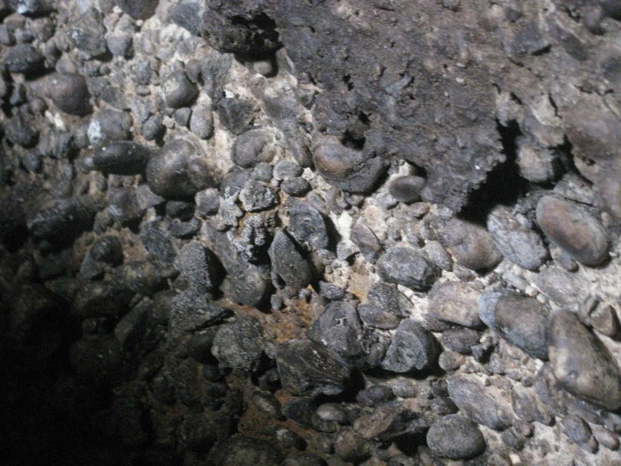
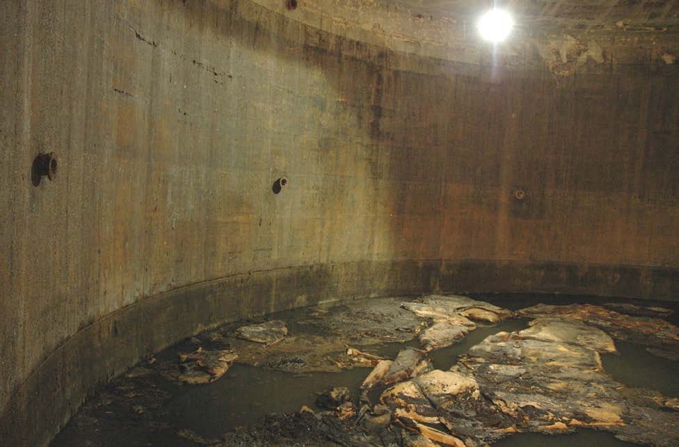
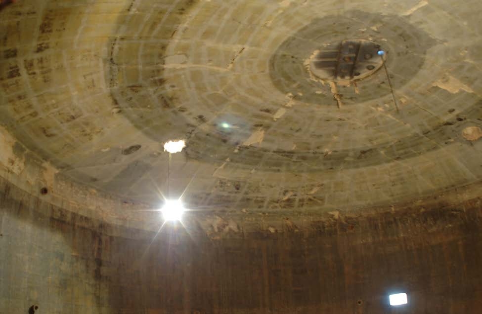
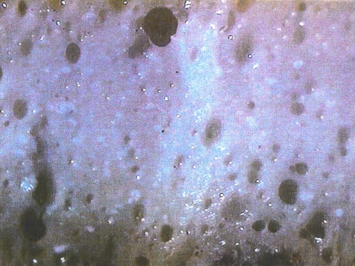
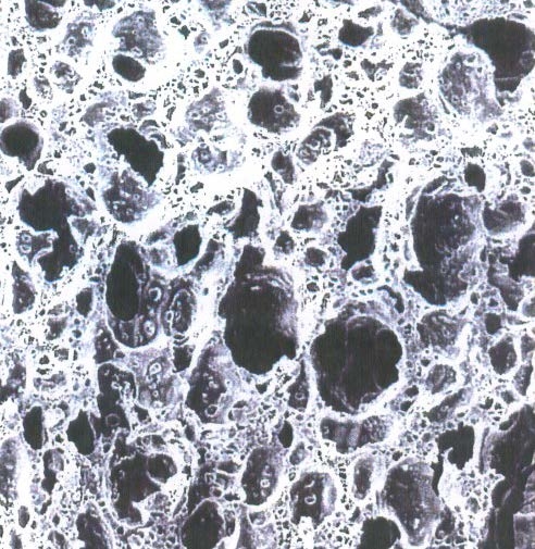
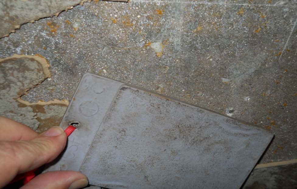
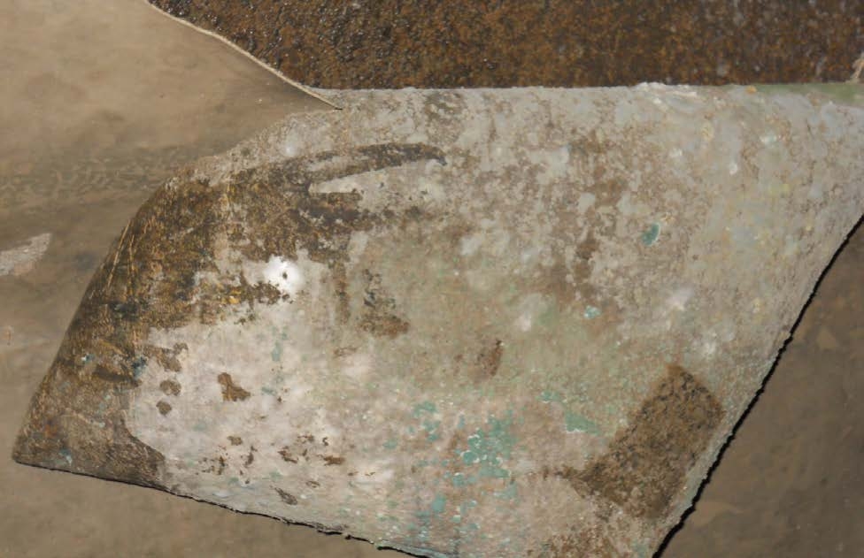
Photo No. 15 and 16 show the prevalent delamination of the PVC/polyurethane lining. As the photographs demonstrate, the failure plane was clearly between the polyurethane adhesive and the primed concrete substrate. Note the presence of polyurethane adhesive backed PVC sheets on the floor of the digester in Photo No. 15. Close examination of the disbonded lining revealed that the polyurethane adhesive was sponge-like, brittle, and had mostly not adhered to the concrete. Photo No. 17 shows a magnified view of the polyurethane adhesive from the failed lining. The adhesive, when properly cured, is flexible much like a polyurethane sealant. Based on well documented technical literature, experience, and further laboratory examination, it was concluded that the cause of the coating failure was the presence of excessive moisture in the concrete substrate. The isocyanate (co-reactant in the polyurethane adhesive) reacted with that moisture (water) and produced carbon dioxide gas as a by-product. The CO2 gas bubbles formed created the sponge-like characteristics of the polyurethane adhesive.
To confirm the expected cause of the coating failure, further analysis was performed. In the laboratory, the two polyurethane adhesive components were mixed and applied to a concrete block which had been soaked in water for 24-hours and then surface dried. A chemically activated PVC sheet was applied over the wet polyurethane adhesive. Within a few hours, foaming occurred in the polyurethane adhesive coating producing a sponge-like, non-flexible consistency. Photo No. 18 shows a microscopic view of that laboratory replication sample. Note the close resemblance to Photo 17 of the failed coating sample taken from the digester.
Another fact supporting the conclusion that excess moisture from the concrete caused the coating failure involved the condition of the polyurethane adhesive between the overlapped PVC sheets at seams in the failed lining. That material was flexible, well adhered to the PVC sheets, and lacked the foam-like structure of the material which had been in contact with the substrate.
This digester lining failure was not the result of process upset conditions or improper material selection, but rather concrete that was not sufficiently dry for the polyurethane adhesive coating used. Had this not been the case, it is likely that the lining system selected would have performed well even under the more aggressive, low pH upset conditions which can possibly occur in anaerobic digesters.
In concrete digesters with fixed concrete roofs, the most widely used coatings to prevent gas leaks have historically been flexible polyurethanes. These coatings provide crack bridging capabilities for hairline wide cracks at which minimal movement is manifested due to either thermal or hydraulic forces on the concrete. If new cracks form in concrete digester walls or roofs or if manifested movement is substantial, cracks in the substrates will be reflected through the polyurethane coating system. But because most concrete digesters are not internally coated until most drying shrinkage cracks have formed and because digesters are well insulated, reflective cracking is generally not problematic. As such, flexible polyurethane coatings have a long-term track record of successful performance for gas proofing concrete digesters.
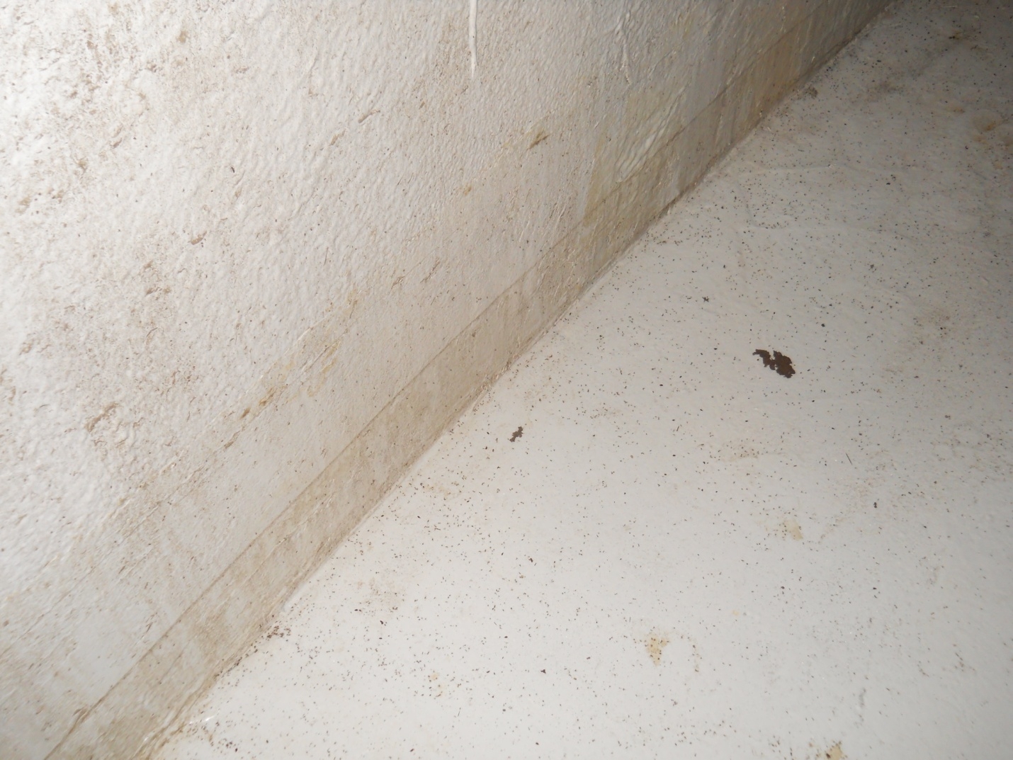
Polyurea coatings, which provide even greater flexibility than many polyurethane coatings, have also been successfully used to line the interior of digesters for gas tightness purposes. When compared to flexible or elastomeric coatings, epoxy coatings do not provide the same crack bridging compatibility. On the other hand, epoxy coating systems generally provide greater tolerance to moisture during cure and better adhesion to concrete substrates than the flexible polyurethane or polyurea systems. This makes certain blended amine cured epoxy coatings ideal alternatives for digester coatings. And with special detail treatment methods, the reflective cracking problem can be overcome. Photo No. 19 shows the successful performance of a specialty epoxy coating on a concrete digester interior after over one year in service.
As noted above, it is typical to only coat the gas storage portion of the top of the digester plus a short distance below the lowest normal operating liquid level to assure gas tightness. Whatever type of generic coating system is selected, proper surface preparation including adequate concrete surface profile must be achieved to ensure good adhesion.
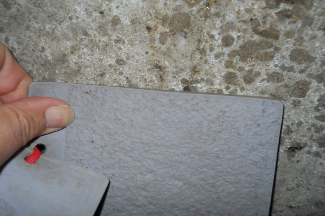
Another real world example of digester coating performance issues involved the premature failure of a flexible polyurethane gas proof coating due to insufficient concrete surface profile and poor coating film quality. The coating failure was manifested by prevalent delamination which began with digester sludge getting behind the coating at pinholes and holidays. Refer to Photo Nos. 20 and 21 which show typical views of this coating failure in a concrete digester after only a few months in service. Photo Nos. 22, 23, and 24 demonstrate that sufficient concrete surface profile wasn’t provided for the coating system in this digester.
Egg shaped digesters (ESDs) are constructed from welded carbon steel and are externally insulated. The external insulation system can be foam glass insulation protected by aluminum jacketing or a polyurethane coating over polyurethane foam insulation. The decision to completely coat the interior surfaces of the ESD or only the gas storage surfaces (plus a short distance below the normal low liquid operating level) must then be taken. This author has seen this choice go both ways. In one instance, all of the internal surfaces of twelve large ESDs were coated with an amine cured epoxy. The digesters were shop fabricated and floated to their place of erection. Photo No. 25 shows an overview of these digesters. The surface preparation (SSPC-SP5) and coating application for those twelve (12) EDSs were also performed in a shop.
After 18 years in service, inspection revealed excellent coating performance with the exception of some areas of coating abrasion down to the steel substrate in mixing zones in the digester. See Photo No. 26. Due to their shape, ESDs provide for better sludge mixing and less grit accumulation in the bottom of the digester when compared to conventional cylindrical digesters. So this raises an important point. Abrasion resistance of coatings used on the interior of ESDs is important. In the case of those twelve ESDs, there is no record of upsets in the operating conditions which would have created low pH exposure conditions. This explains why even at bare steel surfaces, corrosion loses were later found to be negligible.
In another case, two new egg shaped digesters were only intentionally coated in the gas storage zones. Those same two digesters experienced upset conditions early in their service lines. The sludge was not properly digested and low pH conditions (down to a pH of 3.0 to 4.0) prevailed for several months. Aggressive corrosion rates were experienced on the interior carbon steel surfaces of the ESDs. Subsequently, the digesters were removed from service, thoroughly cleaned, abrasive blast cleaned, and properly coated with 20 to 25 mils of a specialty, blended amine cured epoxy coating system. The operating problems were later sorted out, but the recoated digesters operated successfully under low pH conditions for a few months until the biogenesis issues were resolved via pH adjustment using chemical addition. The lesson learned here is clear: the interior carbon steel surfaces of ESDs should be properly coated to prevent severe corrosion damage in the event of upset operating conditions. The additional cost to do this initially would be minimal when compared to the downtime and retrofit costs associated with performing repair and recoating work later.
Another lesson learned with ESDs again has to do with their shape. When ESDs are erected and welded in the field, the inside curvature of the egg shape makes scaffolding access next to impossible where the vessel diameter decreases. This means that rigging the vessel shell for welding, protective coating work, and Q.C. inspection in the field is difficult at best. This is why field welds are typically performed from the outside of the shell only. This is also why good field coating work and related inspection is difficult to achieve on the interior surfaces of ESDs. The main lesson here is that fabrication and coating work should be performed in the shop or on the ground, whenever possible, for ESDs. Furthermore, if ESD shells are to be shop cleaned and primed followed by field topcoating, the maximum recoat time for the shop applied primer must be carefully considered.
To summarize, the following key points can be made:
A. Normal internal operating conditions for anaerobic digesters are not corrosive to carbon steel or concrete. However, under upset or “cold start” conditions, the internal exposure in these vessels can be extremely corrosive. Protective coatings comprise the only viable and cost effective corrosion protection measure for these circumstances.
B. Different digester design types pose varied corrosion problems which can be solved with properly selected and applied protective coating systems.
C. When selecting protective coatings for carbon steel or concrete substrates in anaerobic digesters, the following criteria are essential:
D. For fixed roof concrete digesters, proper drying out of the concrete substrate is essential prior to coating application particularly if flexible polyurethane or polyurea coatings are selected. In addition, reflective movement at cracks in the concrete substrate should be addressed either with flexible coatings or via crack detail treatment if rigid-cured epoxy coatings are chosen.
E. Two common causes of premature coating failures in concrete digesters are lack of adequate concrete surface profile for good coating adhesion and poor film quality (pinholes left in the coating due to outgassing) due to inadequate filling of concrete “bug holes”. Together, these quality misses spell disaster.
F. When designing anaerobic digesters for new treatment plants, engineers should seriously consider specifying protective coating application for all internal wetted surfaces, whether concrete or steel, as “cold start” conditions are likely to be very corrosive for some extended period of time prior to the achievement of bioformation stability in the process.
G. Egg shaped digesters have their own peculiar corrosion protection issues including field accessibility problems during and after construction. Also, experience has shown that abrasion resistance of the coatings used on the interior of ESDs is important. These factors should be considered when new ESDs are designed or existing ESDs are inspected and recoated.
H. Having a technical understanding of how anaerobic digesters operate and are constructed along with knowing some of the major pitfalls associated with past digester corrosion damage and coating performance should help our industry avert premature and costly digester coating failures. Hopefully this paper is helpful in that regard.